C3
Custom Command and Control
Attackers must establish command and control (C2) to gain influence within their target environments in order to pursue their goals and objectives. It is therefore arguably one of the most important parts of the cyber kill chain because without it any payloads that are successfully delivered operate blindly, cannot provide network level pivoting and near real-time interaction. It is no surprise then that organisations have been imposing more controls against what types of communications are allowed from systems and a priority has been placed on defensive teams to be able to effectively detect C2. This is emphasised by two out of the twelve columns of Mitre ATT&CK being related to this area, ‘Command and Control’ and 'Exfiltration’.
The bar has been raised and attackers have been forced to adopt new techniques to hide in plain sight. This evolution of C2 has been observed in real-world attacks with threat actors resorting to using social media and other cloud services to try and blend in with legitimate traffic. Examples of legitimate services that have been seen used in real-world attacks include Outlook [1], Instagram [2][3], Google Drive [4], Photobucket [5], Telegram [6][7].
Red teams performing adversary simulation exercises and purple team engagements should be able to demonstrate similar C2 capabilities whilst maintaining client security. It may be possible to create a proof-of-concept C2 implementations – and many of these have been created and shared within the security community – but there was a lack of a robust framework which allows safe experimentation with communications and was interoperable with industry standard tooling.
C3 was built in response to this requirement. It is a tool that allows Red Teams to rapidly develop and utilise esoteric command and control channels (C2). It's a framework that extends other red team tooling, such as the commercial Cobalt Strike (CS) product, which is supported at release. It allows the Red Team to concern themselves only with the C2 they want to implement; relying on the robustness of C3 and the CS tooling to take care of the rest. This efficiency and reliability enable Red Teams to operate safely in critical client environments (by assuring a professional level of stability and security); whilst allowing for safe experimentation and rapid deployment of customised Tactics, Techniques and Procedures (TTPs). Thus, empowering Red Teams to emulate and simulate an adaptive real-world attacker.
The first proof of concept of C3 was presented at BlueHat v18 by William Knowles and Dave Hartley. Since then it has been refactored and some aspects reimagined into what it is today by a team of developers heavily influenced by members of the MWR Red Team.
Get C3
C3 is open source software maintained by W/Secure, released under a 3-clause BSD license, and is available on Github.
Architecture
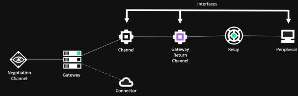
The following terms explain some of the underlying building blocks and associated terminology which form a C3 network:
- Relays – An executable to be launched on a compromised host. Relays communicate through Interfaces either between one another or back to the gateway.
- Gateway – A special relay that controls one C3 network. A C3 network cannot operate without an operational gateway. The gateway is the bridge back to the attacker’s infrastructure from Relays. The Gateway is also responsible for communicating back to a third-party C2 server (such as Cobalt Strike’s Teamserver).
- Channels - An agreed scheme for relays to pass data between each other. For example Slack’s API.
- Gateway Return Channel (GRC) - The configured channel that a relay will use to send data back to the gateway. Note that the GRC may be a route through another relay.
- Interfaces – A high level name given to anything that facilitates the sending and receiving of data within a C3 network.
- Routes – An intended path of communication across relays back to the gateway.
- Peripheral – A third-party implant of a command and control framework. Peripherals talk to their native controllers via a ‘Controller’. For example, Cobalt Strike’s SMB beacon.
- Connector – An integration with a third-party command and control framework. For instance the ‘External C2’ interface exposed by Cobalt Strike’s Teamserver through the externalc2_start command.
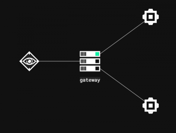
Colours in the C3 network graph also mean different things:
- Green - Active.
- Gray - Inactive for 5 minutes,
- Yellow - Unknown state after Gateway reboot.
- Red - Error.
Practical Usage
C3 is designed to be an easy and intuitive interface that allows users to form complex paths during adversarial simulations. This section provides an in-depth guide of how to use C3, from compilation through to code execution.
Compiling C3
In order to compile C3 Microsoft’s Visual Studio IDE is required. MWR developed C3 with the following dependencies:
- Visual Studio with v141 build tools
- Windows Universal CRT SDK needed
- Windows 8.1 SDK
- .NET Core 2.2 SDK
It should be noted that re-targeting the solution can allow compilation with updated tool-sets. For example, with a fresh install of Visual Studio 2019, opening the C3 solution file will result in the individual components being unloaded:

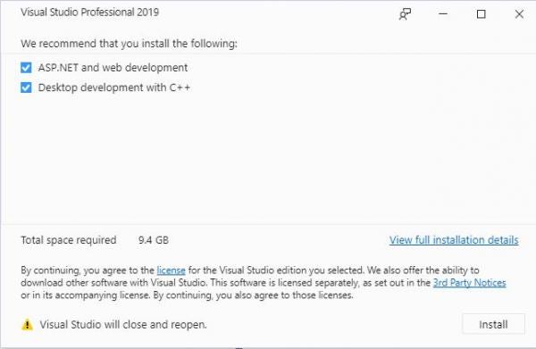
This can be fixed by right-clicking the C3 solution shown in the previous image and selecting “Install Missing Feature(s)”. Visual Studio will identify the missing features and prompt the user to then install them, as shown in the next figure.
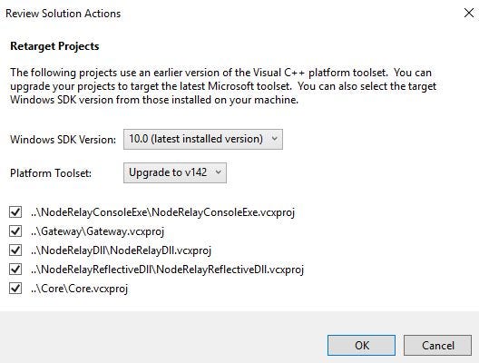
Once reloaded, attempting to compile will result in errors due to the Windows 8.1 SDK not being installed. This can be fixed by right-clicking the C3 solution and selecting “Retarget solution”:
Starting the Server-Side Components
The server-side components consist of a web application and C++ executable that are intended to be run within attacker-controlled infrastructure. Operators should setup this infrastructure by running the web application and gateway controller on a Windows based system.
Starting these components on a Windows system requires several steps to be taken. First, the web application can be started by executing the StartWebController.cmd batch script. Once complete, the command will specify the host and port the web application is being served from – by default this is “http://localhost:52935”, but can be specified by altering the "urls" option.
Next, access the web interface and fill out the required fields in order to download a gateway. An example is shown in the following figure:
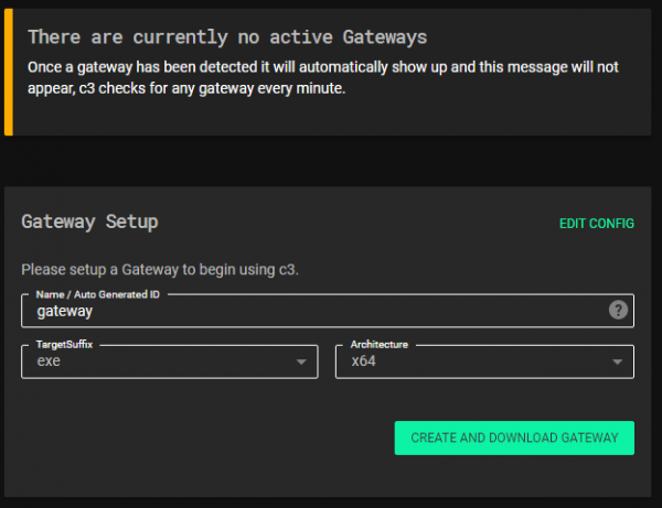
Finally, unzip the downloaded file to a new directory. Execute the gateway binary from the unzipped directory to ensure the correct configuration information is loaded at start up. On execution, the gateway will connect to the web application informing it that it is running. The gateway will appear in the interface and allow the operator to execute commands.
Creating Channels
The simplest way to generate relays is to first create a channel that the relay will communicate with once executed. Channels can be created on the gateway or on relays themselves to allow for pivoting. In both instances, the operator must use the command centre to issue the appropriate command. Relays and gateways can have any number of channels listening.
There are two types of channels:
- Negotiation – facilitates a one to many relationship between a single channel and multiple relays. A relay created from a negotiation channel can be executed as many times as needed. The only limitation is on the rate limiting of the channel communication occurs over.
- Non-negotiation – provides the ability to have one relay communicate with the gateway over a single channel. Single channels are less prone to rate limiting when the appropriate delay is set on the interfaces. Executing a non-negotiation relay multiple times results in undefined behaviour.
The process is as follows:
- Select (double-click) the gateway or relay on which to create the channel.
- Open the command centre screen by selecting the “Command Centre” button.
- In the “Select Command” dropdown, select a command such as “AddNegotiationChannelSlack”.
- Fill out the required information, such as any credentials and application specifics.
- Click the “Send Command” button.
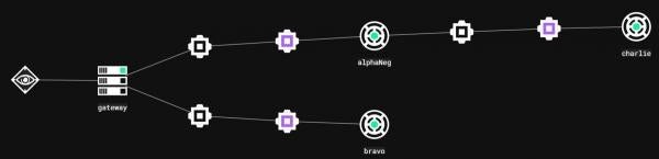
If Auto-Update is selected, the web interface will display the new channel once the gateway confirms it has been setup. If not, the web interface will need to be refreshed before the new channel interface can be seen. The figure below shows a gateway with 3 listening channels, one negotiation and two single channels.
The following video demonstrates setting up a Slack channel on the gateway. Once setup is complete, the gateway will simply listen on the channel for incoming connections.
Generating Relays
Relays are intended to be executed within the target’s estate. Relays have two main purposes, communicating back to the gateway over some Internet based channel, and routing traffic from other relays in the C3 network back to the gateway. If the previous steps were taken during the gateway channel setup process a new relay that can connect to that channel can be generated in only a few clicks.
The process is as follows:
- Select (double-click) the channel for which you want to generate your relay.
- From the “Interface options” select “New Relay” command.
- All of the required information will be automatically completed. At this point the user can specify architecture, type of file (exe, dll) and so on.
- Click the “Create and Download Relay” button.
This is demonstrated in the next video.
Note that as shown, all the relevant information the relay will need to connect to the gateway over the specified channel is automatically filled in. There is no requirement to keep track of input and output IDs, channel names or API tokens.
Finally, either through a previously established C3 network, or some other payload delivery mechanism, the relay must be uploaded and executed on a victim system. Once executed, the relay will establish a gateway return channel. The next video demonstrates a relay generated from a negotiation channel being executed multiple times. Note that the “negotiation process” causes a new interface to be generated on the gateway for each connection.
Staging a Cobalt Strike Beacon
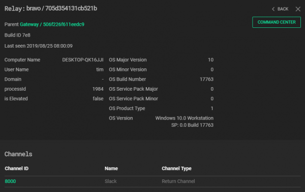
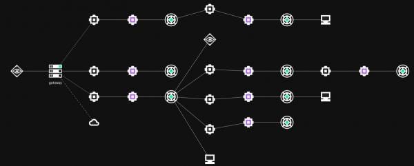
By default C3 relays do not automatically stage a beacon on execution. This provides operators flexibility and control over which endpoints in an organisation they want to fully compromise. The C3 UI displays which relays have a beacon running through a Peripheral (computer icon). In the figure below, “alpha” has a beacon whilst “bravo” does not.

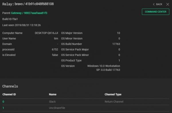
Whilst a beacon is not staged by default, the relay will return metadata about the compromised endpoint when it calls home for the first time. The next figure shows the information obtained from the “bravo” relay.
In order to get a beacon and gain access to the wide variety of functionality provided by the Cobalt Strike framework, the following steps need to be taken:
Step 1: Set up an external C2 listening port on the Teamserver
- Create a file named “ExternalC2.cna” with the following content:
externalc2_start("<teamserver-ip>", 2222);
- Load this script into Cobalt Strike by clicking: Cobalt Strike -> Script Manager -> Load and select the “ExternalC2.cna” file.
- The teamserver will now bind TCP port 2222 and wait for connections.
Note: if a fresh copy of Cobalt Strike is being used, an arbitrary listener needs to be created prior to using the external C2 port. Creating this listener forces Cobalt Strike to generate its keys.
Step 2: Connect the C3 Gateway to the external C2 set up in Step 1
- Connect the gateway to the Cobalt Strike teamserver by executing the “TurnOnConnectorTeamServer” command on the gateway (this is only required once).
- Select the relay that a beacon should be staged on by double clicking it.
- Open the command centre and select “AddPeripheralBeacon”.
- Click “ok” if the information is correct.
At this point, the gateway will request an SMB beacon from the teamserver as per the ExternalC2 specification. This will then be forwarded on through the C3 network until it reaches its destination, where it will be executed in memory.
Warning: executing the “exit” command in Cobalt Strike will terminate the beacon and the relay. Use the C3 “Close” command on the peripheral command centre to force termination whilst keeping the relay alive.
The next video demonstrates staging a Cobalt Strike beacon through C3.
Advanced Usage
C3 Lateral Movement
A key feature of C3 is the ability to extend the network using non-traditional vectors. This network can be made up of a variety of communication mediums, can contain complex routing paths, and allows for redundancy to be built in on the fly.
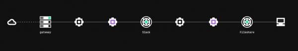
The following diagram shows a simple example where the “Slack” relay is used to route traffic for the “Fileshare” relay, which has a beacon running in memory. In this instance, sending a command to the beacon through Cobalt Strike causes the gateway to send a message over Slack. The “Slack” relay reads this message, understands that it is intended to be forwarded, and writes the message to the UncShareFile channel. Finally, the “Fileshare” relay reads this message and writes it to the SMB beacon.
In general, the C3 network can be extended with three steps:
- Create a new listening channel on a relay
- Generate a new relay that will connect to that channel
- Execute that relay on a new host.
Manually Routing Relays
Routing is one of C3’s most powerful features. Allowing red teamers to create complex paths through a network. Routing in C3 can also facilitate a high degree of redundancy. Whilst powerful, this feature is complex, and requires some familiarity with C3 and its core concepts. Specifically, an operator must understand how to address a relay’s interface through its ID.
Every relay in the network has access to its own routing table. This is a dictionary that translates the RouteID (AgentID of remote relay and DeviceID attached to it) into the DeviceID of the local channel. When a relay receives a packet to forward it will search its routing table and send it to the device associated with the routing entry.
Consider the scenario illustrated in the figure below. The Bravo relay is setup to be a redundant C2 channel, whereas AlphaNeg and Charlie are the main foothold. Now consider the case that an operator decides to route traffic from Charlie through Bravo.
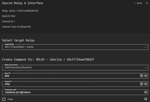
Bravo can be used to create a route between Charlie and the gateway. The first step is to create a new channel on Bravo (Note – negotiation channels cannot be used for routing). Next, on the newly created channel select “Connect Relay” from the “Interface Options”. This is a special command that creates a new channel on a specific relay, in the next figure, “Connect Relay” is being called targeting Charlie.
Once executed, Charlie will have a new interface:
The next step involves “linking” these new interfaces. This is performed through C3’s routing functionality. Relays and gateways have access to the “CreateRoute” command, which takes three parameters: RouteID, DeviceID, and Neighbour.
The RouteID is used to address a relay on a specific channel. It is made up of the AgentID and ChannelID and is of the form “AgentID:ChannelID”. In the next figure, Bravo has an AgentID of 41b91c848f688108 and two channels: 0 and 1.
A RouteID that targets Bravo’s new interface would therefore be “41b91c848f688108:1”. The DeviceID is the outgoing interface for packets being routed matching the RouteID. To create the route on Charlie, the “CreateRoute” command is executed as shown in the next figure. Note that Bravo’s route table must also be updated in the same way.
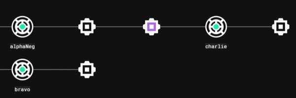
The “Neighbour” parameter is set to True as this route will be connecting two relays. Once sent, Bravo and Charlie will be connected through the new Route. The C3 Web Interface should have Tree View disabled for users to see this new graph:
At this point the connection between Bravo and Charlie is not used. The Gateway's routing table has not been updated, and Charlie's Gateway Return Channel (GRC) is currently the route back through AlphaNeg. The cycle illustrated in the previous figure can be leveraged in two ways:
- Send data in a clockwise fashion from the Gateway.
- Provide redundancy should communication to AlphaNeg fail.
In order to send data clockwise through the network, Charlie's GRC must be set to the interface connected to Bravo. This can be performed in Charlie's command centre using the "SetGatewayReturnChannel" command, specifying the DeviceID (the ID of the Channel connected to Bravo).

Redundancy is provided by the route back from Bravo. Should AlphaNeg terminate for some reason, Charlie would be left with a "dangling" GRC (assuming the GRC hasn't been changed).
At this point the Gateway's routing table needs to be updated to tell it how to route packets to Charlie. This action requires knowledge of: Charlie's Agent ID, the Device ID of the interface connected to bravo, and the Device ID of the interface the Gateway should send packets out of. The Agent ID and first Device ID form the Route ID as previously described. The second Device ID tells the Gateway to send packets to Bravo. For example, Charlies Agent ID is "38cf1724eaf38d2f" and has a UncShareFile channel of Device ID 1 connected to Bravo. As such, Charlie's route ID from the Gateway through Bravo is "38cf1724eaf38d2f:1".
Next, the Device ID of the local channel on the Gateway can be determined by identifying the Channel ID of the interface connected to Bravo. In the figure below, the Gateway routes packets to Bravo (who's Agent ID is "41b91c848f688108") through the outgoing Slack interface with Channel ID 3. Therefore the Device ID for the new route to Charlie is also 3.
The "CreateRoute" command on the Gateway is executed using this information. Next, the old route to Charlie through AlphaNeg needs to be deleted, this ensures the gateway only uses the new route. Routes can be deleted by hovering over the route options and selecting "Delete", as shown below:
Only at this point is it possible to set Charlie's GRC, as the Gateway has a new working route to send Charlie commands. The final network looks as such:
The following video demonstrates creating routes for redundancy. The scenario is as follows:
- Two relays exist: Alpha and Bravo.
- Bravo has a Cobalt Strike beacon as well as a redundant UNCShareFile channel.
- Bravo’s connection back to the gateway is closed.
- C3 routing is used to reconnect to Bravo through Alpha.
Warning: Manually routing in C3 is a complex process that, if done incorrectly, can result in an ill-formed and unusable network. It is strongly recommended operators practice routing in a development environment prior to any live use.
Pivoting/Port-Forwarding
By design Cobalt Strike’s ExternalC2 specification makes connection orientated activities difficult. This is due to the fact that SMB beacons have no concept of “sleep” time (they cannot be made interactive). Instead, an SMB beacon will only send data after it receives a message from the teamserver. Additionally, SMB beacons are only able to send 1MB of data within each response. As a result, should a beacon attempt to send >1MB of data, only the first chunk will be sent, at which point the beacon will block until it reads a new message from the teamserver.
One solution to this problem could be to force the teamserver to send lots of messages to the beacon. The simplest message a teamserver can send is a no-op. The rate at which a teamserver can send these no-op messages is determined by the “block” parameter in the ExternalC2 specification. Therefore, setting the “block” parameter to a small value would result in a large volume of no-op traffic, causing the beacon to quickly respond with the data it was trying to send.
This solution however is not ideal. A small “block” value will result in a large volume of traffic across the C3 network. Subsequently messages will be delayed heavily by rate limiting. This can hinder an operator’s ability to perform any connection orientated activity – such as port-forwarding. C3 is designed in such a way that allows such activities, with some caveats. This has been achieved through several key design decisions:
- Playing no-op ping-pong with the gateway and teamserver.
- Having the relay and gateway read and write messages at the same time.
- Forcing the relay to send all of the data it has by replying with no-ops to any non-no-op message.
The only limitation for pivoting is the delay for packets to traverse the C3 network. The following video shows the "fileshare" relay with a beacon in memory. This relay is setup to route traffic through another relay over Slack.
Contributing to C3 - Channel Development
Current C3 Channels
MWR have developed a number of channels that will be released on an “on pull-request" basis. This means that MWR will release additional channels as and when members of the community submit channels they have written themselves. As part of the initial release, MWR have provided access to the Slack and UNCShareFile channels. When combined, these allow for external access and internal pivoting.
The following channels are also ready to be released:
- EWSTask
- Trello
- NamedPipe
- OneDrive365RestFile
- Outlook365RestTask
Contributing a new channel is designed to be as simple as possible. Developers do not necessarily need to understand the inner workings of C3.
Developing a Channel
The following tutorials describe the process of C3 channel development in a step by step matter, along with detailed explanations and best practices. This section will demonstrate how to create a channel that utilises Windows named pipes for communication. It will make use of MWR’s helper class in order to achieve communication. The purpose of using this class is to abstract away from how to communicate with named pipes and focus on the C3 framework.
Basic Tutorial
This tutorial focuses only on a bare minimum effort required to develop a C3 Channel. First, open the C3 solution file in MS Visual Studio and add a new *.cpp file to the “Common” project. The Preferred location is: “Src/Common/MWR/C3/Interfaces/Channels” or its sub folder.
Next, open the newly created file and enter a type that will represent the Channel. An example for a channel named MyChannel is as follows:
#include "StdAfx.h"
#include "Common/MWR/WinTools/Pipe.h"
struct MyChannel : MWR::C3::Interfaces::Channel
{
MyChannel(MWR::ByteView arguments) : m_Pipe("MyChannelPipeName"_bv)
{
}
size_t OnSendToChannel(MWR::ByteView packet) override
{
return m_Pipe.Write(packet);
}
MWR::ByteVector OnReceiveFromChannel() override
{
return m_Pipe.Read();
}
protected:
MWR::WinTools::Pipe m_Pipe;
};
A breakdown of this code is as such:
- The first line is required by Visual Studio for projects using precompiled headers.
- The MyChannel struct definition publicly inherits from a CRTP called Channel<>, which is required by the C3 framework in order to register the Channel.
- Next there are three overridden methods – OnSendToChannel, OnReceiveFromChannel and a constructor that takes one MWR::ByteView argument. These methods are used to bind the channel’s functionality with the C3 framework.
- Note the m_Pipe member variable, this is a wrapper for Windows named pipe.
- For this basic tutorial the argument for the MyChannel constructor is ignored. Instead the named pipe member variable is initialised with a hardcoded name. Note that _bv is a literal for MWR::ByteView.
- OnSendToChannel’s implementation simply takes its parameter (packet) and writes it to the pipe.
- OnReceiveFromChannel reads from the pipe and returns the buffer.
With this file added, the solution can be recompiled. Re-starting the C3 web application is all that is required after compilation to use the newly created channel.
Advanced Tutorial
This tutorial will cover more advanced features that can allow developers to create complex channels with a rich feature set. This will be demonstrated by extending the previously written named pipe channel. This section will cover:
- How to define input parameters, allowing users to provide dynamic pipe names from the UI.
- How to add a custom command.
- How to use Log functionality and the built-in string obfuscator.
- How to set a channel’s initial “Update Delay Jitter” values.
- How to perform refactoring, ensuring developers keep to code standards.
- Discuss requirements of overridden methods and other implementation details.
Adding a Channel’s Create Arguments
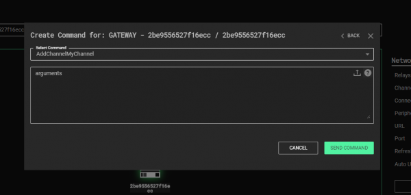
The previously created Channel from the Basic tutorial has a flaw in its implementation – the pipe name is hard-coded. This not only prevents it from being reused multiple times in a single C3 network, but also disables some useful features. For example, this flaw prevents the channel from being used as a Negotiation Channel. Additionally, as C3 has no way of knowing the creation parameters of MyChannel, it will default them to a single binary blob of data:
The UI can be made to explicitly ask for each parameter and validate their values in a few steps. First, the type of m_Pipe is changed from MWR::WinTools::Pipe to MWR::WinTools::DuplexPipe. The duplex pipe allows for two identifiers to be assigned for every MyChannel instance. Whilst not definitively required, this design decision adds a number of benefits.
Before further discussion is given as to the named pipe channel, it is important to understand what a Double-ID design is and how it operates. The core concept is to address two communicating interfaces with a unique pair of IDs – as opposed to using one identifier for the pair.
As an example, consider a file system Channel implementation and the various ways communication could be designed:
- Model 1 - share a file for each pair of C3 Channels.
- Model 2 - assign a pair of files for each pair of Interfaces.
- Model 3 - use a single file (shared by everyone), then assign each party an ID, and precede each packet with two related IDs (e.g. AB if Interface A is talking to Interface B, CA if C is sending a packet to A, etc.).
- Model 4 - use a single file then assign each party two unique IDs (inbound and outbound) and precede each packet with that ID.
All implementations are valid and will work with the C3 Framework, but some features won’t be available for Model 1. The figure below provides a visualisation of sample incompatible and compatible channel designs.
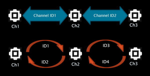
As can be seen on the bottom diagram (compatible version), “Ch1” Interface’s output ID is the same as “Ch2” Interface’s input ID, and vice versa. The same goes for “Ch2” and “Ch3” pair. This diagram will now be applied to MyChannel – every MyChannel instance will get an input ID and an output ID assigned to them.
To begin, the definition of the GetCapability() static method provides a JSON representation of MyChannel’s capabilities:
static ByteView GetCapability()
{
return R"({
"create":
{
"arguments":
[
[
{
"type": "string",
"name": "Input ID",
"min": 4,
"randomize": true,
"description": "Used to distinguish packets for the channel"
},
{
"type": "string",
"name": "Output ID",
"min": 4,
"randomize": true,
"description": "Used to distinguish packets from the channel"
}
]
]
}
})";
}
This optional method needs to return a JSON string that contains customisation details of the channel. In this instance, the JSON informs C3 what kind of arguments the channel needs in order to be created (by defining the "arguments" array within the "create" object).
There are 2 parameters defined, both need to be at least 4 characters long and random values should be assigned to them when the channel creation dialog appears in the UI (this also enables the randomise button next to the argument’s field). Both parameters are of type string. Other types supported by C3 include: “int8“, “int16“, “int32“, “int64“, “uint8“, “uint16“, “uint32“, “uint64“, “float“, “boolean“, “binary“ and “ip“ (IP address). The name field is used to label the argument in the UI and the description is rendered when a user hovers their mouse cursor over the field’s help icon. There are two other properties that haven’t been specified here: max and defaultValue. As their names might suggest, they define the maximum length of a string argument (or the maximal value of an arithmetic argument) and its default value.
Note: Using "randomize": true requires the channel to explicitly specify the min value.
Note: The use of an array for Input and Output ID is important. This tells C3 that the arguments are identifiers and should be swapped for complementary channels (channel’s 1 Input = channel’s 2 Output and vice versa). Developers should avoid the use of an array for other arguments they choose to define for a channel.
The next step in this tutorial involves updating MyChannel’s constructor to read the new arguments:
MyChannel(ByteView arguments)
: m_Pipe(arguments.Read<std::string, std::string>())
{
}
Note: It is up to Channel’s developer to ensure that the type parsed in Read is the same type as the one declared in the JSON returned by GetCapability (e.g. "type" : "int16" should be parsed later as args.Read<int16_t>()).
Note: The Read method “moves” ByteView according to the length of data that was read and allows for multiple parameters to be read at once (e.g. auto[integer, text, real] = args.Read<int8_t, std::string, float>()).
Note: std::string and MWR::ByteVector types are stored in a buffer in a way that keeps track of their length (by preceding them with 4 byte-long size).
Note: Arithmetic types are always stored in the little-endian byte order.
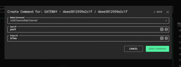
As in the basic tutorial, compile the whole C3 solution, go to the root folder of C3 and run the StartWebController.cmd script. The channel creation command window in the Web UI should now look as such:
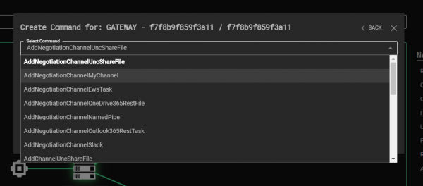
Because this channel uses the Double-ID design, additional features of C3 will be unlocked. Firstly, a new command will be provided in the user interface that can be used to create a Negotiation channel:
Secondly, C3 will add the “Connect Relay” option to all instances of MyChannel, which automatically attaches a complementary MyChannel instance (fills in swapped Input and Output identifiers) for a selected Relay:
Finally, C3 will add the “New Relay” option for all existing MyChannels, which creates a new Relay payload with a complementary initial Channel:

Creating a Custom Command
Every Interface provides two built-in Commands: Close and UpdateDelayJitter. However, channel developers are able to add their own custom commands, by enlisting them in the static GetCapability() method:
static ByteView GetCapability()
{
return R"({
"commands":
[
{
"name" : "Test Command",
"description" : "Logs provided text.",
"id" : 0,
"arguments" :
[
{
"type" : "string",
"name" : "Message",
"description" : "Message to Log."
}
]
}
]
})";
}
The JSON buffer that GetCapability returns defines one Command labeled “Test Command”, which takes one string argument. The "id" field (specified as equal to 0) is needed to distinguish between custom commands, and is required to be in the range 0 – 32767.
In MyChannel, an overriden implementation of OnRunCommand is defined:
ByteVector OnRunCommand(ByteView command) override
{
auto commandCopy = command;
switch (command.Read<uint16_t>())
{
case 0:
return TestCommand(command);
default:
return __super::OnRunCommand(commandCopy);
}
}
This method simply parses the first two bytes of the command buffer as the command id. If its value is different than all command ids that have been registered then the base class’ OnRunCommand method is called – to ensure handling of internal Commands remains intact. Therefore, if the command id is 0, the TestCommand method will be called by MyChannel.
ByteVector TestCommand(ByteView args)
{
Log({ OBF("Custom Command : ") + args.Read(), LogMessage::Severity::DebugInformation });
return {};
}
The TestCommand method adds a debug text entry to C3’s Log. DebugInformation is used which is rendered in a Relay’s console window only when compiled in debug mode. The message consists of two elements: a hard-coded text "Custom Command : " and a string that is provided by a user in the UI. Note the use of the OBF macro, this is used to encrypt strings at compile-time, which are decrypted at run-time only when required. Also of note is that the TestCommand handler returns an empty ByteVector as there’s nothing to send back to the Gateway.
After rebuilding the solution once again and launching C3 the Test Command becomes available in MyChannel’s Command Center:
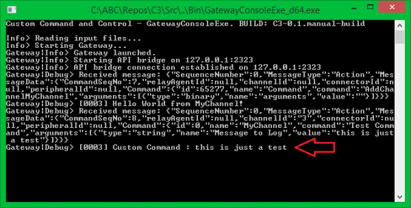
Putting it all Together
After developing a functionally working channel, the next stage is to refactor the code. The MyChannel type is still quite small, but for larger classes it’s common to split the implementation between a header and a compilation unit file. For MyChannel this involves adding a new MyChannel.h file in the same location as MyChannel.cpp. This also involves embracing the channel with the appropriate namespace declaration - MWR::C3::Interfaces::Channels. Finally, doxygen-style documentation is added to improve readability. MyChannel.h is then as such:
#include "Common/MWR/WinTools/Pipe.h" //< For MWR::WinTools::Pipe.
namespace MWR::C3::Interfaces::Channels
{
/// Implementation of a Named Pipe Channel.
struct MyChannel : public Channel
{
/// Public constructor.
/// @param arguments factory arguments.
MyChannel(ByteView arguments);
/// OnSend callback implementation. Called every time attached Relay wants to send a packet through this Channel Device. @see Device::OnSend.
/// @param packet data to send through the Channel.
/// @return number of bytes successfully sent through the Channel. One call does not have to send all data. In that case chunking will take place, Chunks must be at least 64 bytes or equal to packet.size() to be accepted,
size_t OnSendToChannel(ByteView packet) override;
/// Reads a single C3 packet from Channel. Periodically called by attached Relay. Implementation should read the data (or return an empty buffer if there's nothing in the Channel waiting
/// to read) and leave as soon as possible.
/// @return ByteVector that contains a single packet retrieved from Channel.
ByteVector OnReceiveFromChannel() override;
/// Processes Commands addressed to this Channel.
/// @param command a buffer containing whole command and it's parameters.
/// @return command result.
ByteVector OnRunCommand(ByteView command) override;
/// Example Command handler. It must be registered/described in GetCapability. @see MyChannel::OnRunCommand.
/// @param args Command's arguments.
/// @returns ByteVector Command result.
ByteVector TestCommand(ByteView args);
/// Describes Channels creation parameters and custom Commands.
/// @return Channel's capability description in JSON format.
static ByteView GetCapability();
/// Explicit values used as the defaults for Channel's UpdateDelayJitter. Values can be changed later, at runtime.
constexpr static std::chrono::milliseconds s_MinUpdateDelayJitter = 100ms, s_MaxUpdateDelayJitter = 100ms;
protected:
/// The pipe wrapper object.
MWR::WinTools::DuplexPipe m_Pipe;
};
}
And the implementation within MyChannel.cpp:
#include "StdAfx.h"
#include "MyChannel.h"
/////////////////////////////////////////////////////////////////////////////////////////////////
MWR::C3::Interfaces::Channels::MyChannel::MyChannel(ByteView arguments)
: m_Pipe(arguments.Read < std::string, std::string > ())
{
Log({
OBF("Hello World from MyChannel!"),
LogMessage::Severity::DebugInformation
});
}
/////////////////////////////////////////////////////////////////////////////////////////////////
size_t MWR::C3::Interfaces::Channels::MyChannel::OnSendToChannel(ByteView packet)
{
return m_Pipe.Write(packet);
}
/////////////////////////////////////////////////////////////////////////////////////////////////
MWR::ByteVector MWR::C3::Interfaces::Channels::MyChannel::OnReceiveFromChannel()
{
return m_Pipe.Read();
}
/////////////////////////////////////////////////////////////////////////////////////////////////
MWR::ByteVector MWR::C3::Interfaces::Channels::MyChannel::OnRunCommand(ByteView command)
{
/// Check if it's a custom or internal Command, then call appropriate handler.
auto commandCopy = command;
switch (command.Read < uint16_t > ())
{
case 0:
return TestCommand(command); //< Our custom Command.
default:
return __super::OnRunCommand(commandCopy); //< An internal Command.
}
}
/////////////////////////////////////////////////////////////////////////////////////////////////
MWR::ByteVector MWR::C3::Interfaces::Channels::MyChannel::TestCommand(ByteView args)
{
Log({
OBF("Custom Command : ") + args.Read < std::string > (),
LogMessage::Severity::DebugInformation
});
return {};
}
/////////////////////////////////////////////////////////////////////////////////////////////////
MWR::ByteView MWR::C3::Interfaces::Channels::MyChannel::GetCapability()
{
return R "({
"create":
{
"arguments":
[
[
{
"type": "string",
"name": "Input ID",
"min": 4,
"randomize": true,
"description": "Used to distinguish packets for the channel"
},
{
"type": "string",
"name": "Output ID",
"min": 4,
"randomize": true,
"description": "Used to distinguish packets from the channel"
}
]
]
},
"commands":
[
{
"name": "Test command",
"description": "Logs provided text",
"id": 0,
"arguments":
[
{
"name": "Message",
"description": "Message to Log."
}
]
}
]
})";
}
There are two new elements in the header file that have not previously been discussed - s_MinUpdateDelayJitter and s_MaxUpdateDelayJitter. All C3 Interfaces are updated periodically with some jitter. This is called the Update Delay Jitter and is specified by setting two range values in the UI – minimal and maximal. If both values are the same, then Update Delay Jitter is constant. If they differ, each delay is randomised in the range specified by min and max. Default (initial) Update Delay Jitter is equal to 30ms. If an interface needs to specify a different initial value, then it should set it by defining s_MinUpdateDelayJitter and s_MaxUpdateDelayJitter public constexpr static members – as demonstrated above. Update Delay Jitter can be changed at run-time with an Interface’s Commands.
Note: When using third-party APIs for Command and Control (such as Slack), the values set in s_MinUpdateDelayJitter and s_MaxUpdateDelayJitter directly contribute to avoiding heavy rate limiting.
Channel Development Summary
The tutorials provided here have discussed all the elements required to develop a channel in C3. MyChannel was intended to be as simple as possible in order to focus on C3 specifics. Channels can often be far more complicated and require longer implementations of OnReceiveFromChannel and OnSendToChannel methods. As such, the following details should be considered:
- OnReceiveFromChannel is fired periodically, while OnSendToChannel is fired only if there’s something to send though the Channel. Bear in mind that calls to both methods could be made at the same time from two different threads. Implement appropriate synchronization mechanisms if they share any non-atomic objects.
- OnSendToChannel returns the number of bytes successfully sent to the channel. If it’s less than the size of the provided packet, but more than 63, automatic chunking kicks in. If a channel sends less than 64 bytes, C3 will attempt to resend the packet and therefore call OnSendToChannel with the same buffer again, while the complementary Channel automatically rejects the packet.
- OnReceiveFromChannel should retrieve only one packet at a time or return an empty buffer (in case there’s nothing to read). An option to return more than one packet is planned to be added in future C3 releases.
- Both methods should perform the minimal number of operations and leave as soon as possible. There is a possibility to add single-threaded Relays to C3 in the future, which means that only one thread of execution will be shared between all interfaces and all their methods. Bear in mind that one stalling Channel will block the whole Relay, until this method returns. That’s why if a Channel’s overrides (especially updates - OnReceiveFromChannel) require more time to execute, the implementation should be split into smaller pieces, Update Delay Jitter should be increased, and those pieces invoked in an interlaced manner.
Conclusion
If you have made it this far in this introduction to C3 you hopefully see how the tool can be used to simulate more complex and creative communications scenarios. Additionally, you too can hopefully see how new communications channels can be added with relative ease. Overall, we hope that red teamers and defensive teams can leverage the toolset to better enable organisations to defend themselves against threat groups' evolving tradecraft.
We hope to continue development of C3 ourselves and with the help of the community from this release forwards. Through our own testing of the tool and our own brainstorming we have seen things which work really well such as the modularity, resilience of command and control networks created and the dynamic nature allowing red teams to adapt during an operation. We have also noted things we want to improve and for users to be conscious of. These include the size of relay artefacts and the fact that in-memory artefacts for some of the communication modules could disclose keys and credentials for third-party services. These are areas we will continue to work on and need to be considered during operational use.