Sniff, there leaks my BitLocker key
By Henri Nurmi on 21 December, 2020
Introduction
Full disk encryption is one of the cornerstones of modern endpoint protection. It is not only an effective method to protect sensitive data against physical theft, but it also protects data integrity against tampering attacks. If this protection method could be compromised without significant effort, it would break the fundamental idea of endpoint protection.
Over time there have been many different physical attacks against full disk encryption, such as Cold Boot attacks [0][1] that we have previously researched. In addition, various attacks based on TPM interface sniffing [2] or DMA [3] have been used to gain access to an encryption key.
Even though the game [4] is typically over if the attacker has unrestricted physical access to a target computer, and I entirely agree with this, how many companies take these types of attacks into account in their threat models? In addition, I think there are still different nuances in how difficult it should be to carry out the required attack – attackers also have a budget.
In this post, we research a sniffing attack against an SPI interface of Trusted Platform Module (TPM) by using publicly available tools at a reasonable cost. In addition, we release a tool which extracts the BitLocker key from the sniffed SPI traffic.
Previous work
TPM is often used to seal the full disk encryption key, and the chip itself is typically protected against a various range of different attacks. However, the communication between CPU and TPM is not encrypted by default, which leaves it vulnerable to sniffing attacks.
Capturing communication of TPM is not a new idea. For example, D. Andzakovic [2] demonstrated a BitLocker key extraction from the LPC bus, and J. Boone [5] researched an interposer attack against the I2C bus. However, there were no public research on sniffing the TPM communication from the SPI bus.
Overview of BitLocker
BitLocker is Microsoft's full disk encryption feature for Windows, which was introduced in Windows Vista. Starting from Windows 10 Version 1511, BitLocker uses AES-XTS encryption algorithm to encrypt the whole volume. By default, the key length is 128 bits but it could also be configured to use a 256-bit key.
The architecture of BitLocker involves multiple keys. A full volume encryption key (FVEK) is used to encrypt the BitLocker-protected volume. This key is encrypted by a volume master key (VMK), and the encrypted FVEK is stored in the metadata of the volume. Finally, VMK is encrypted by various protectors, and the encrypted VMK is stored in the metadata (similarly to the FVEK). Only one protector is required to decrypt the VMK by default.
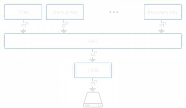
This architecture allows an easy way of re-keying the system if any of the protectors are compromised, since only a new VMK needs to be generated and the FVEK re-encrypted with the new VMK. This mechanism eliminates the requirement to re-encrypt the entire volume.
More technical details about BitLocker can be found in BitLocker's Technical Overview [6].
Overview of Trusted Platform Module
Trusted Platform Module is a cryptographic coprocessor, which implements a predefined set of cryptographic operations, secure key storage, and a set of Platform Configuration Registers (PCRs). TPM is one of the commonly used protectors for BitLocker.
One of the key advantages of TPM is the ability to release a piece of a secret after platform integrity is verified. This verification is achieved by measuring each step in a boot process and storing the measurements in PCRs. The secret can be locked to the specific PCR values, and it could only be released if the current state of PCRs matches those original values. BitLocker uses TPM to seal VMK, and the key can only be unsealed if the boot process has not been tampered with.
Usually, the TPM chip is a discrete module on the motherboard, and CPU communicates to the TPM chip through the Platform Controller Hub (PCH) or a southbridge. The TPM specification describes the three different communication interfaces: LPC, SPI, and I2C. In addition, the two different IC package types are allowed for TPM, which are TSSOP-28 (on the left) and QFN-32. The QFN-32 package makes the sniffing attack more complicated since it is harder to get physical contact with its pins.
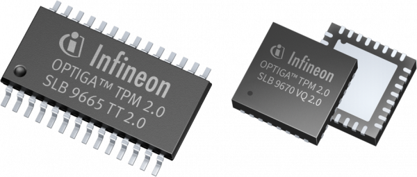
Source: [7] and [8]
Sniffing SPI bus
Serial Peripheral Interface (SPI) is a synchronous serial communication protocol supporting full-duplex communication with high-speed clock frequencies. It uses master-slave architecture, where the master device always initiates the communication. The SPI bus consists of four wires:
SCLK: Serial Clock
MOSI: Master out Slave in (data from the master)
MISO: Master in Slave out (data from the slave)
SS: Slave select (selects the active slave device)
Multiple slave devices can be connected to the same SPI bus. However, in this situation, each slave device requires its own SS-line as showed below.

A logic analyzer that can capture four signals simultaneously is required to sniff the bus. The minimum sampling rate depends on the speed used in the bus. The TPM standard defines that the TPM chip with SPI interface shall support the 10-24 MHz clock frequency range. However, the standard also states that faster clock frequencies could be supported. Keep in mind that we should use at least four times faster sampling rate than the used clock speed on the bus.
As described above, the form factor of the TPM chip is either TSSOP-28 or QFN-32, and they both are tiny packages. The TSSOP package could be probed with some high-quality probes. However, the QFN package requires soldering wires to the IC since it does not have legs. In addition, motherboards typically contain test points or debug ports connected to the TPM data bus, which could also be utilized to sniff communication. It would be an advantage if the sniffing attack could be performed quickly and without special tools.
The laptop usually needs to be disassembled to access the TPM chip, which is not very practical. However, a UEFI firmware is often stored in an SPI-based flash chip, which typically has a SOIC-8 package. This type of package can be hooked very easily with regular probes. Because multiple devices can be attached to the same SPI bus, the flash chip and the TPM chip likely share the same bus. In addition, the flash chip is commonly accessible only by removing a back cover or a keyboard, and therefore the flash chip is a perfect target to sniff the communication in the SPI-bus. This tactic eliminates the need for soldering, and the attack can be performed within a reasonable time.
The target is a few years old Dell Latitude E5470 laptop which is running BitLocker enabled Windows 10, and TPM protects VMK without an additional PIN-code. In this specific model, both TPM and a flash can be accessed by removing the back cover, as seen in the picture below.
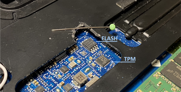
The Nuvoton NPCT650JAOYX TPM 2.0 chip comes with the QFN-32 package, and as we see, it is impracticable to probe the chip directly. We can check with a multimeter that the clock pin on both ICs are connected together, confirming that they share the same SPI bus. As we can see, the SOIC-8 package looks huge compared to the QFN-32. The flash chip has the following pinout, which guides the placement of the probes.
*-----------+
--| SS |--
--| MISO |--
--| SCLK |--
--| GND MOSI |--
+-----------+
As described above, each SPI-device has its dedicated SS-line, but in our case, the target laptop has only two devices connected to the bus. Therefore, the SS-line of TPM can be constructed by taking a negation from the SS-line of the flash chip. The SS-line can also be just ignored. However, there is for the possibility of decoding flash communication as TPM communication in that situation.
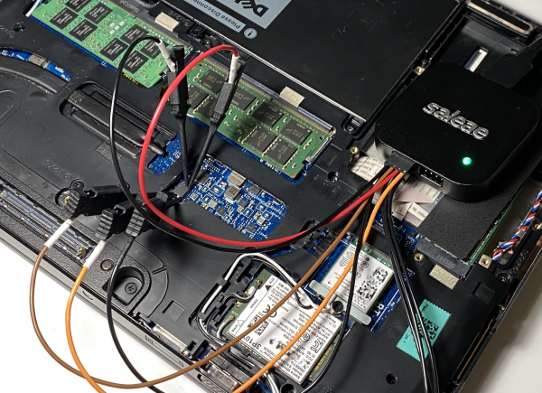
I captured the SPI signals with the Saleae Logic Pro 8 logic analyzer, which is capable of recording four signals up to 100 MHz. The wide terminal pitch of SOIC-8 package allows an effortless way to hook the probes, and the whole capture process can be performed under one minute.
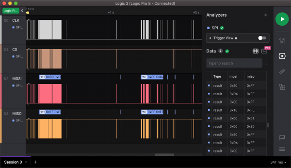
The Logic 2 application supports SPI decoding out-of-the-box. The only caveat is to remember that the SS-line is inverted. Fortunately, the decoding options of Saleae allow us to choose whether the chip is selected when the SS-line is high or low. The screenshot below shows decoded MOSI and MISO byte streams from the capture.
Looking for a needle in a haystack
Before we can continue, we have to discuss what we are looking for. At the moment, we have two decoded byte streams, which present only the raw data in the bus. The bytes in the MOSI stream are traffic from CPU to TPM, and for the bytes in the MISO stream it is the other way around.
In Section 7.4, PC Client Platform TPM Profile Specification [9] describes the SPI protocol for the TPM 2.0 chip. The key elements here are read and write transactions which both look almost the same. The transaction starts when the host sends a command byte, followed by three bytes long address. After this, 1-64 transaction data bytes are sent either by CPU or TPM, depending on the transaction type. However, TPM can insert a wait state between address and data bytes to hold off the transfer. The TPM chip inserts the wait state by driving the MISO line low on the last bit of the address, and the line is driven to low until the TPM chip is ready to receive or transmit data. The read transaction is shown below.
Source: [9]
The command byte encodes the transaction type and size of the transfer. When the most significant bit in the command byte is 1, the transaction type is read. Otherwise, the type is write. The six least significant bits decode the transfer size from 1 to 64 bytes. The table below shows the whole structure of the protocol.
+------------+---------+----------------------------------+
| Byte Index | Usage | Notes |
+------------+---------+----------------------------------+
| 0 | Command | bit[7] = type -> 1=read, 0=write |
| | | bit[5:0] = size of transfer |
| | | 00_000 -> 1 byte |
| | | ... |
| | | 11_111 -> 64 bytes |
| 1 | Address | Address[2] |
| 2 | Address | Address[1] |
| 3 | Address | Address[0] |
| 4 | Data | Data[0] |
| ... | | |
| n | Data | Data[n] |
+------------+---------+----------------------------------+
Given that information, we can confirm that we are able to capture TPM transactions. The screenshot below shows the one byte read transaction to the 0xD40018 address, where TPM sent back 0x90 as a result.
Logic 2 cannot parse TPM SPI transactions by default. However, it supports custom high-level analyzers, which can further analyze the decoded SPI traffic. I wrote an analyzer that decodes TPM transactions from the SPI stream and shows them in Logic 2.
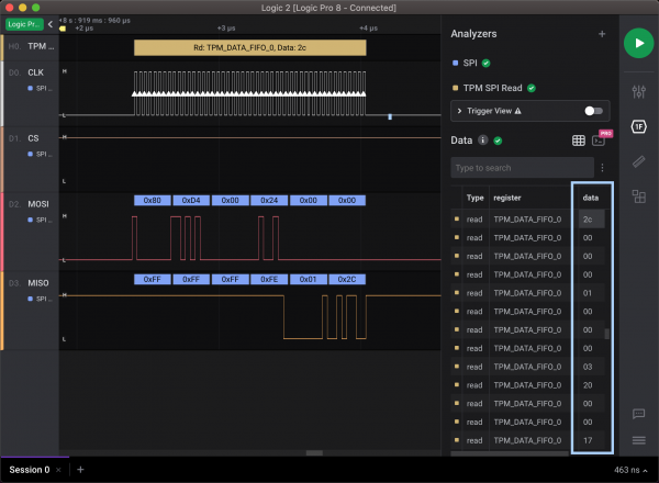
Although TPM has multiple different registers, we are only interested in the TPM_DATA_FIFO_x ones. These FIFO registers act as buffers between the host and the TPM when data for commands or responses are exchanged. Therefore, dumping the content of FIFO registers is enough to catch the unsealed key. In addition, BitLocker uses only Locality 0, which limits the monitored registers to TPM_DATA_FIFO_0, and this specific register decodes to the address 0xD40024. A parsed read transaction from that register is shown below.
The remaining problem is identifying VMK from the byte stream. Luckily, BitLocker structures [10] are publicly available. The VMK metadata entry has a format that is similar to an FVE metadata entry as described in Section 5.3. The VMK entry consists of the following fields.
+--------+------+-------------------+
| offset | size | description |
+--------+------+-------------------+
| 0 | 2 | entry size |
| 2 | 2 | entry type |
| 4 | 2 | value type |
| 6 | 2 | version |
| 8 | 4 | encryption method |
| 12 | 32 | key |
+--------+------+-------------------+
This information allows us to create a search pattern, which matches possible VMKs on the byte stream. We know the details below based on the above documentation:
entry size: 0x002c - 0x0c (metadata) + 0x20 (key)
entry type: 0x0000 - None, entry is a property
value type: 0x0001 - Key
We cannot be sure of version and encryption method fields, but we have limited possibilities for them. Therefore, we can use the following pattern to search for the start of a VMK entry. Note that the fields in a header are using little-endian.
2c00000001000[0-1]000[0-5]200000As the screenshot shows below, we can definitely see the above structure in the TPM_DATA_FIFO_0 stream. The following 32 bytes starting with 0x17 are the actual VMK.
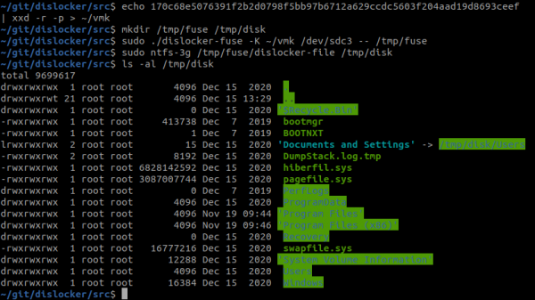
Once the VMK is extracted, the drive can be decrypted and mounted. The latest version (0.7.3) of Dislocker [11] supports decrypting the volume by using VMK. Therefore, we do not have to parse and decrypt the FVEK key manually. The following screenshot shows the mounting procedure.
Automated approach
Even though Proof of Concepts are awesome, proper weaponizing usually takes the attack to a whole new level, and as we stated at the beginning of this post, the real advantage comes if this can be performed with minimal effort. Therefore, I decided to automate the attack process as far as possible. The toolchain consists of the following parts:
- Custom High-Level Analyzer for searching VMK entries from TPM transactions.
- Docker container, which includes all the necessary tools to mount the drive just by giving VMK.
The workflow with the tooling is as follows:
- Sniff the SPI bus and extract VMK.
- Remove the drive and attach it to the attacker's machine or boot the target directly from a USB-stick if allowed.
- Decrypt and mount the drive.
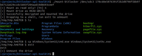
The video below show how the analyzer is able to extract the VMK from the sniffed data. The key can be then passed to the mount tool which decrypts the content and drops you to a shell where you are able to modify the volume content.
You can find the above tooling on GitHub.
Mitigation
Instead of using the TPM-only protector, one of the following should be used to mitigate this attack [12]:
- TPM with PIN
- TPM with startup key
- TPM with startup key and PIN
In the TPM with PIN mode, TPM requires an additional PIN code before VMK is unsealed. It should be noted that the key can be sniffed even if the PIN code is used. However, the attacker must be able to sniff the bus at the same moment when the PIN code is entered.
If unprivileged users can access any used BitLocker's keys or protectors, they can perform local privilege escalation (LPE) by modifying the content in the volume. Therefore, this attack allows for easy LPE for insiders. It is worth noting that the same LPE applies if users knew their recovery keys.
A startup key adds an extra layer where VMK can be decrypted only if both TPM and the startup key are presented. The startup key can be stored on a removable device, for instance, a USB-stick.
TPM 2.0 supports something called parameter encryption, where the first parameter in a TPM command or response is encrypted. However, BitLocker does not support this feature at the moment, and J. Boone showed in his research that it has its own caveats.
Conclusions
We demonstrated the BitLocker key could be also extracted from the SPI traffic very easily without expensive tools. The attack requires physical access with the target machine only for a few minutes by using automated tools.
References
[0] Tomi Tuominen & Timo Hirvonen - All your encrypted computer are belong to us
https://www.youtube.com/watch?v=NdVpwS5e6Cg
[1] Adam Pilkey - The Chilling Reality of Cold Boot Attacks
https://blog.f-secure.com/cold-boot-attacks/
[2] Denis Andzakovic - Extracting BitLocker keys from a TPM
https://pulsesecurity.co.nz/articles/TPM-sniffing
[3] Jean-Christophe Delaunay - Practical DMA attack on Windows 10
https://www.synacktiv.com/en/publications/practical-dma-attack-on-windows-10.html
[4] Microsoft - Ten Immutable Laws Of Security (Version 2.0)
https://docs.microsoft.com/fi-fi/archive/blogs/rhalbheer/ten-immutable-laws-of-security-version-2-0
[5] Jereymy Boone - TPM Genie
https://www.nccgroup.com/us/our-research/tpm-genie/
[6] Microsoft - BitLocker Drive Encryption Technical Overview
https://docs.microsoft.com/en-us/previous-versions/windows/it-pro/windows-server-2008-r2-and-2008/cc732774(v=ws.10)
[7] Infineon - SLB 9665
https://www.infineon.com/cms/en/product/security-smart-card-solutions/optiga-embedded-security-solutions/optiga-tpm/slb-9665tt2.0/
[8] Infineon - SLB9670
https://www.infineon.com/cms/en/product/security-smart-card-solutions/optiga-embedded-security-solutions/optiga-tpm/slb-9670vq2.0/
[9] TCG PC Client Platform TPM Profile Specification for TPM 2.0
https://trustedcomputinggroup.org/wp-content/uploads/PC-Client-Specific-Platform-TPM-Profile-for-TPM-2p0-v1p05p_r14_pub.pdf
[10] libyal - BitLocker Drive Encryption (BDE) format specification
https://github.com/libyal/libbde/blob/main/documentation/BitLocker%20Drive%20Encryption%20(BDE)%20format.asciidoc
[11] Aorim - Dislocker
https://github.com/Aorimn/dislocker
[12] Microsoft - BitLocker Countermeasures
https://docs.microsoft.com/en-us/windows/security/information-protection/bitlocker/bitlocker-countermeasures