Guiding black-box CAN fuzzing with electromagnetic side-channel analysis
1. Introduction
Modern vehicles are complex distributed systems that contains dozens of ECUs (Electronic Control Unit), which are heavily interconnected through the vehicle bus. The ECU’s main task is to control different vehicle subsystems, i.e. engine management, braking systems, safety features, light control, environment management, and infotainment. The vehicle bus acts as a main communication backbone line that interconnects these ECUs, often through the Controller Area Network (CAN) protocol. Ensuring security and robustness for the communications over the CAN bus, as well as preventing unauthorized control of the ECUs through this bus are essential security controls to integrate during development of a vehicle. Vulnerabilities in this area could lead to severe impact on safety and security, including the potential for unauthorized access, tampering, or even taking control of critical vehicle functions. In the past year, we have seen multiple cases when compromising the ECUs via CAN bus access allows attacker to gain remote control or steal the vehicle. These recent occurrences demonstrate that security testing of automotive ECUs is an essential task, and conducting a security assessment of the CAN bus interfaces of the ECU is important. Standards such as ISO/SAE 21434 and UNECE R.155 and R.156 introduce formal requirements for cybersecurity testing in automotive.
One essential part of such assessment is fuzzing. In this article, one corner case of such activities will be discussed, when fuzzing is performed during blackbox-style assessment, with minimum or no information about CAN IDs supported by the ECU.
While there are multiple methods to address such a scenario, including reverse engineering the ECU firmware, another possible approach proposed in this article would be guided fuzzing with the aid of electromagnetic side-channel analysis.
2. CAN fuzzing as a part of automotive ECU security assessments
In general, fuzz testing of the target device could help in the identification of potential vulnerabilities, non-security bugs and safety problems.
The ISO/SAE 21434 – cybersecurity engineering for road vehicles standard requires manufacturers to perform systematic risk assessments and implement appropriate security measures throughout the whole lifecycle of the vehicle. By conducting systematic and comprehensive fuzz testing of the ECU CAN bus interfaces, vendors can identify and resolve potential vulnerabilities, bugs, and safety deficiencies. Two main approaches of fuzzing CAN bus can be distinguished: mutational and generational.
Mutational fuzzing means making random changes to pre-recorded genuine CAN messages that are used by ECUs to communicate with each other. In its simplest form, this might simply bitflip byte(s) of the original message. More sophisticated approaches could vary from injecting random values up to complex heuristics that could detect specific protocol fields such as, control sums, Message Authentication Control fields and data structures within the CAN message body. Mutational-based fuzzing could reveal potential issues in the handling of unexpected or malformed messages by the target system.
Alternatively, generational fuzzing is creating new messages from scratch, based on a known CAN messages specification or set of predefined rules. E.g., in more sophisticated cases, it allows to send all possible types of CAN messages that would be processed by the device, thus providing much higher coverage compared to the mutational approach.
Several tools exist that could be used for fuzzing the CAN bus. From simple cangen from can-utils, sophisticated open-source projects like CANtoolz and caringcaribou, to commercial tools from Vector, Interpid Control Systems and Synopsys.
Regardless of the fuzzing approach, mutational or generational, the result would be sequences of messages that are being sent to the target .
Next to generating messages, it is equally crucial to monitor the target during the testing to detect the discrepancies in its behavior specifically to determine whether fuzzing samples are causing some issue in the target. Common monitoring techniques might include, but not limited to:
Debugging: When debug access is present on the ECU, it is possible to directly monitor the execution and parsing of the CAN messages.
Heartbeat monitoring: ECUs often send periodic "heartbeat" messages on the CAN bus to indicate their operational status. If these messages are interrupted or change significantly during fuzzing, it might indicate a crash or malfunction in the ECU. Any periodic messages from the ECU could be treated as a heartbeat in the context of monitoring.
Requesting a reply using a valid CAN message: Some ECUs may respond with specific messages or acknowledgments upon receiving certain commands. Periodic sending of such messages and verifying that correct replies have been received code indicate whether the ECU is working correctly during fuzzing.
Observing traffic on exposed interfaces - including CAN: The presence of abnormal messages, or corrupted traffic, might be the symptom of an unexpected firmware behavior.
Side-channel monitoring such as power consumption changes. Significant fluctuations in the power consumption of an ECU during fuzzing can indicate that the unit is experiencing issues, such as crashes or resets.
The different monitoring approaches will give a different level of insight. E.g. in the case of debugging, in-depth analysis of the results individual messages produce is possible, whereas in the case of heartbeat monitoring, it is only possible to validate whether the unit remains operational.
3. Blackbox challenges
In the previous section, we described how it is important to understand both how the unit behaves under normal operation, as well as have a mechanism to identify anomalies. Therefore, having more information about the target, and better debug access, will make the analysis more effective.
Unfortunately, in the real world, the availability of this information or access might be limited, and it is not uncommon for projects to be unable to provide timely and complete information such as message specifications, traffic dumps, debug access or source code. Even if sample traffic captures from a live system are available, it is possible that not all extracted CAN messages can be processed by the target unit. In this situation, mutational-based fuzzing techniques could be used to identify additional valid messages supported by the unit.
It is however not certain that a sent CAN message would effectively be processed. In many cases, valid CAN messages (CAN IDs that are being processed by the ECU firmware and potentially activate some functionality) do not generate any immediate direct or indirect feedback. In these circumstances, performing effective fuzzing of the CAN bus with appropriate coverage poses a significant challenge.
Let's simplify the task that we're facing in a black-box situation: to be more effective in fuzzing, we need to know a valid CAN ID. This will allow us to narrow the fuzzing sample space, which increase the possibility of triggering the bug or vulnerability during fuzzing.
When none of the described monitoring approaches is applicable e.g., because the behavioral changes for the device between receiving valid and invalid CAN ID are too small, we need an alternative method to externally detect whether a test message is being processed, or discarded, by SoCs firmware
In such a case, if there is access to the firmware binaries, one could perform reverse engineering and extract CAN IDs from them. Moreover, you could even find automated tools and plugins for modern disassemblers that could aid with this task. Alternatively, if there is access to the final product (fully assembled car) that includes the target ECU, it might be possible to extract CAN IDs from live traffic recordings, by putting the vehicle in the various operating modes.
In the absence of the physical vehicle, firmware binaries and any sort of documentation for the valid messages accepted by the ECU, one of the last options could be performing electromagnetic side channel analysis (EM-SCA) while fuzzing the target.
4. Side-channel analysis to the rescue
Side channel analysis is the area of system testing and evaluation that uses non-invasive techniques to obtain some information from the target. This information, or information leaks, could reveal some possible insights about target internal processes. The technique originally emerged as a part of cryptanalysis that targets the physical implementation of cryptographic algorithms. In this discipline, information is being leaked via unexpected channels, including timings, power consumption or electromagnetic (EM) radiation, and even temperature and sound. This information could be used to exploit the cryptographic implementation. It should be noted that here the algorithm itself is not a target, but rather the weaknesses in its software or hardware implementation, or maybe both.
EM side channel analysis (EM-SCA) focuses on the EM radiation emitted by the target during its operation. All electronic components, from capacitors and transistors, and up to complex integrated circuits, are emitting EM waves during their normal operations. These waves could be captured and analyzed, to extract potentially relevant information about system behavior. The big advantage for EM-SCA is that it can be performed non-invasively, by placing a probe on top of the target system or System-on-Chip (SoC) while it is performing the operations we're interested in. In general, by using a probe and an oscilloscope or data acquisition device (DAQ), signals from the target are collected. These signals might reveal some details of the underlying process. For example, in cryptanalysis, the attacker could correlate the EM emissions with execution of specific instructions, or instruction blocks in the cryptographic algorithm implementation.
The differences in the captured EM signals during EM-SCA are due to software/algorithm implementations executing different logical branches, which means that different transistors and other components are activated in a different order when processed on the SoC. This makes it possible to distinguish the system behavior by comparing the EM-pictures of the system when it reacts to some external input. In our case, this external input would be CAN messages.
An additional benefit of EM-SCA for such tasks is that, unlike power analysis, it is not necessary to heavily modify the target board to capture SoC power consumptions, reducing the time and effort needed. Also, modern SoCs could have up to dozens of power lines, which would make power analysis quite a tricky task. In practice, this would result in a tiresome process, which cannot be applied in many projects where invasive techniques are not allowed.
5. CAN messages processing and EM emissions
Different ECUs might have different approaches for processing CAN messages. For example, implementations could vary from switch-case constructs to a set of high-level abstractions that ends up as a handler table. When compiled into assembly, this results in a comparison of the ID against a static value or a table lookup, followed by a JMP to the specified handler code or continuing execution. In case a received CAN ID is not handled by the target, the firmware will immediately continue to execute its normal operations. However, in case a valid messageis received, a different flow of instructions will be executed, and hence the EM-picture changes accordingly. This is happening because different transistors, in a different order, would be activated within the SoC.
To ease further explanations, we will use the following terminology onwards:
Invalid EM-picture: the EM-picture recorded for an invalid CAN message which is unprocessed or unknown to the target ECU.
Valid EM-picture: the EM-picture recorded for a CAN message which is processed by the target ECU.
Candidate EM-picture: the EM-picture for a message with a CAN ID for which we’re trying to determine whether it is valid or invalid.
Let's look at this picture which shows two EM picture captures, invalid (orange) and valid (blue):
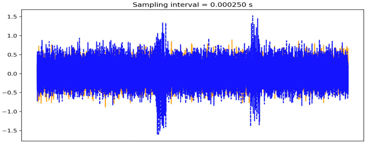
As can be seen from the EM picture, the processed CAN message is significantly different compared to the declined CAN message. For demonstration purposes, we selected a corner case, where the valid ID is 7df which is the diagnostic (UDS) arbitration ID for this ECU. Hence, the differences between picture captures are significant and visible to a naked eye. However, these differences could be detected for much less expressed cases when we compare the EM-pictures using proper mathematical distance and threshold.
Following this approach, traversing the full CAN ID space allows us to identify which CAN IDs are valid and processed by the unit and guide our fuzzing efforts in this manner. So, we could follow the following algorithm to implement this:
1. Record the EM-picture for a known invalid message.
2. For each CAN IDs:
2.1. Record EM-picture for the candidate message
2.2. If EM-picture is significantly different from invalid one, record this CAN ID as potentially valid and as a target for fuzzing.
It is important to always compare signals that are time-aligned. In other words, signals that have been recorded from the same starting point of the parsing logic. To achieve this, it is convenient to set-up a trigger, which starts capturing the signal right before the CAN message will be processed by the ECU. For this, we can use an oscilloscope supporting CAN triggering ora purpose-specific board, equipped with an FPGA or a fast SoC/MCU, running a custom firmware capable to initiate such trigger. The probes for such a device could be connected either to the CAN bus near the candidate message generator, or to an RX/TX pin of the CAN transceiver on the message generation device. Once the trigger condition is reached, the EM picture for processing of candidate message is recorded.
Even when using extremely precise and fast equipment, results will still slightly drift. This happens because of the noise or insufficient speed/precision in the trigger device, or more often because of the unpredictable nature of the execution flow in modern ECUs. These are not hard real-time systems, but rather a soft one as most of them are using multitask OSes which might not process the CAN message at the exact same time after receiving it from transceiver. One way to mitigate this effect is by averaging the signal. Instead of capturing just one sample as a response to a candidate CAN message, we capture a multiple of each and use averages instead. Additionally, we could normalize (i.e., using standard score) each distinct sample before averaging. This might help to minimize the imperfection of the setup and triggering, as well as compensate for signal drift.
Unfortunately, we cannot afford to average over too many samples due to the EM environment around us not being stable and constantly changing. Fluctuations in the power lines, change of the temperature or humidity in the room, operating vacuum cleaners or microwaves on another floor, a sudden increase in wireless traffic – all these could affect the observations. A lab environment with a fully isolated room providing stable environment conditions reduces the impact of such issues. Lacking this, recording more samples over time to further average the invalid EM-picture of a CAN message will result in the overall environment changing so that even if a candidate message is also invalid, the distance between these two averages would be too big.
Averaging therefore requires careful fine tuning on how many samples we want to average. If we use too many, the EM environment might change too much while we are capturing all of them; and if we use too few, the unpredictable nature of execution flow in ECU might be insufficiently compensated. An additional consequence of this is that we cannot record an invalid EM-picture once, and then compare all candidate EM-pictures to it, we need to re-record it each time before capturing the candidate EM-picture, since the EM environment tends to constantly change.
6. Practical method and measuring bench setup
Considering all prior context, we could describe our method as follows:
1. Find a CAN ID that creates an EM measurement for an invalid (unprocessed) CAN message.
2. For every other candidate CAN ID:
2.1. Record M normalized EM captures for the known invalid CAN message and average them. We could label the result as I.
2.2. Record the same number (M) normalized EM captures for the candidate CAN message and average them. Let's label the result as C.
2.3. If the distance (i.e., Euclidian distance) of I to C is above some threshold value, consider C as valid and record it for further fuzzing.
Now we need to understand the specifics of capturing the EM signals. In our approach, we use:
Generator, which generates either an invalid or candidate CAN message to the target, depending on the step of the method.
Trigger device, which issues the signal that the CAN ID reached a target point in the execution flow.
Measurement device, which records the EM picture from the MCU/SoC on the target that processes the CAN messages.
As a generator, we're using a custom script that traverses the specified CAN ID range and fills the message body with random data. Other approaches can be considered here depending on how much is known about the target. Our script implements CAN messages generation, setting the trigger, sending them on the vehicle bus, and processing the measurement results.
As a trigger device, a custom FPGA or fast microcontroller/SoC board can be used. Alternatively, an oscilloscope with CAN trigger, which could be controlled remotely (e.g., via LXI/SCPI) would also work perfectly. Any device that could output an external trigger quite fast would be enough for the job. For example, Keysight DSOX1xxx or DSOX2xxx for triggering on CAN messages, and Siglent SDS2xxx Plus for CAN FD worked well for our purposes. The generator, before sending the message on the bus, needs to set up the trigger on the oscilloscope via USB or Ethernet (using e.g., SCPI commands) and arm it. Once a message with such CAN ID appears on the line, the oscilloscope will trigger it on Ext.Trig. output and the measurement device will start recording the EM capture.
As a measurement device, you need an oscilloscope or DAQ. The device must have enough resolution and buffer size, to properly record the signal coming from the EM probe. In our setup, PicoScope 5XXX USB scope series showed good enough performance. We used various resolutions, and 12-bit+ was sufficient in most cases.
The type of EM probe that should be used is crucial. There are two main types of probes: H-field (magnetic) and E-field (electric) probes. H-field probes are usually better suited for these purposes because they are less sensitive to the specific orientation of the probe with respect to the target device SoC. The probe should be highly sensitive and have a high frequency range to capture the target EM radiation. The probe's tip size will depend on target SoC and should be selected based on whether we want to measure signals from the device at whole, or just from a specific part of the SoC.
The EM probe should be placed very close to the target device, no more than a couple of millimeters away, to pick up the electromagnetic radiation generated by the device. It is important to fix the probe (and target) position in a stationary way during all measurements, since even a slight change of the position could affect the results.
Usually the signal coming out from the probe is “weak”, you need to use a signal amplifier, which increases its amplitude (i.e., voltage). If possible, it will be also beneficial to reduce external noise, by applying shielding to the setup. Additionally, as already mentioned, controlling environmental factors such as temperature and humidity can help ensure more reliable and accurate results.
We were able to achieve good results even using the unexpensive EM probe and LNA from the NewAe's ChipWhisperer's basic Planar H-probe kit (CW505). Using this probe with proper positioning and reducing external noise will allow you to discover processed CAN IDs on slow (<100MHz) MCUs with good precision. For more versatile setups or challenging targets, we use TBPS01-TBWA2/20dB kit from TekBox, which includes 20dB LNA, three H-field probes of different sizes and one E-probe.
You could see one variation of our setup in action on the following photo:
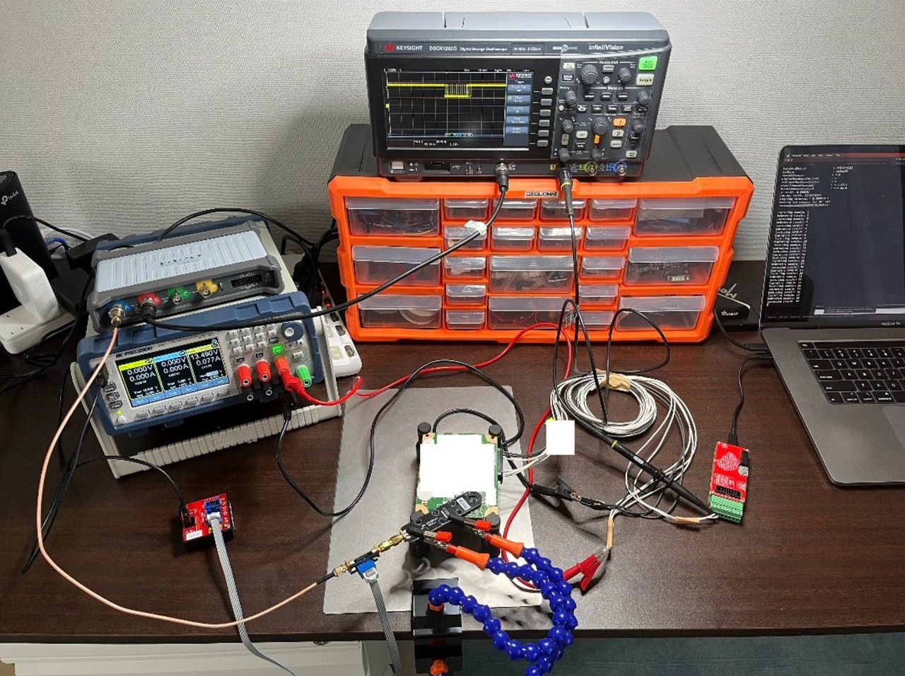
As can be seen from the picture, the capture the EM-picture is performed using NewAE HPROBE which is paired with the OpAmp. The signal goes into the PicoScope 5XXX series. The trigger is provided by Keysight DSOX1202G oscilloscope.
7. Conclusions
In this article we described available approach based on EM-side channel analysis that could be used to discover valid CAN IDs that are processed by a target ECU. This technique could be used to improve efficiency and effectiveness of the fuzzing procedures, especially in all black-box scenarios where CAN message maps are not available. Instead of sending a high number of messages on the bus which are immediately discarded by the unit, we can follow a more targeted approach focused on the messages that are actually processed by device. The cost of such a setup is reasonable and most of the equipment is already present in the average hardware or automotive testing lab.
This method is not a universal guarantee for success, and it has failed us in the past. This was usually due to the high operating frequency of the target MCU/SoC, or too much noise generated by other components around the chip. Still, it is a useful tool that is nice to have in our arsenal for full black-box security assessment projects of automotive ECUs.
That said, we very much prefer our clients to simply share the list of supported CAN IDs a certain unit supports, it is much more straight forward, faster and leads to better results.