Opening Up the Samsung Q60 series smart TV
By on 20 December, 2019
WithSecure has a long-standing record of success in ZDI’s pwn2own contests. This year’s event in Tokyo was no different – the same team scored major points across the board, pwning everything from the TP-Link router all the way up to Xiaomi mobile phone handset.
However, we also felt that some of the targets offered this year would benefit from having some more general analysis work done and documented publicly, to lower the barrier to entry for other researchers to find vulnerabilities. In particular, the Smart TV category stood out to us, since smart TVs are typically complex devices which operate in a fairly privileged position in a household. It doesn’t take much imagination to see how dangerous a remotely-hacked smart TV can be, since they are usually equipped with microphones (and occasionally webcams), and if we examine the contents of the “Vault 7” leak from 2017, we can see that various governments thought the same:

Despite this, there is relatively little known about the internals of most smart TVs. While an open-source firmware for Samsung TVs exists (https://wiki.samygo.tv/), compatibility is extremely limited, supporting only pre-2011 TVs. Because of these reasons, we chose to analyse the Samsung Q60R smart TV in depth.
At the same time, a separate F-Secure team were analyzing the same device, their intention being to find the quickest route to 0day to win the competition (a task they ultimately succeeded in, using a Javascript bug for device compromise).
In this blog post, we aim to document how we went about performing our analysis, in enough detail that it can be replicated, and expanded upon, by the community at large. Our intention is to lower the barrier to entry for analysis of the smart TV. We will not touch on the success of the team that ultimately entered pwn2own or their methodology.
Collaborative setup
Our first hurdle was one of practicality – once we buy the TV, how can we make it available to a team of geographically-dispersed hackers? Most of our research was based in our Singapore office, but we were joined on the work by staff in Poland and the UK. Furthermore, the team needs 24/7 access to the devices (everyone knows the best hacking always happen at 2AM, fuelled by energy drinks!).
We could somewhat mitigate this by using Samsung’s development tool chain, which includes an emulator for the TV. Some investigation of this revealed it to be running a modified version of qemu and an x86 build of the TV’s guest OS. This is very useful for our research, but we noted a number of disparities between the emulated environment and the actual TV, and so we wanted to ensure that the TV hardware was used whenever possible.
The first step in this is obvious – we set up a VPN to the TV. This involved adding an isolated network segment dedicated to TV research, in order to isolate it from company traffic. This meant we could all connect to the TV itself, which was equipped with an Ethernet connection. However, remote hackers couldn’t use the TV’s remote control, which made things difficult – in particular, the TV would power itself down after some inactivity and the remote control would be required to power it back up. We clearly needed a way to emulate the remote control remotely.
Those unfamiliar with smart TVs may be surprised to learn that the Q60’s remote control is not a simple infrared emitter. A cursory look inside the remote control unit reveals a complex device:
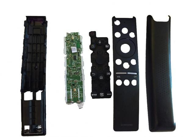
Under that sticker there is an UE878NMEG IC, equipped with WiFi. There are also two microphones on this board, along with a 4mbit flash chip and a wealth of debug ports, along with the usual infrared LED. Due to time constraints, we didn’t analyse the remote control in depth, but feel this area is interesting and ripe for more research. We noted that each TV is supplied with a remote control which is paired to that individual TV, implying that there is some cryptography going on somewhere – perhaps a remote control can be emulated via WiFi and used to attack all nearby TVs.
Taking the quickest route to collaborative working, we re-used the work that the community had already produced in the form of infrared controller boards. We bought a “USB IR Toy”, which is a pre-programmed PIC microcontroller attached to an infrared transmitter and receiver hardware, and used the open-source LIRC software to drive it. With the addition of a simple Python web interface, anyone with access to the VPN could control the TV via an emulated “remote control”.
Obviously, having a remote control isn’t very useful unless you can see what’s on the screen of the TV. We simply bought a cheap USB webcam, and used the Motion project to expose the image to a web browser.
Finally, we installed MediaWiki for collaborative note-taking.
We did debate the necessity of a “hard” power control, for remotely turning off the mains power supply to the TV in the eventuality that it crashes or becomes unresponsive. This was to be achieved using either a server-style switched PDU, or with a consumer-level IoT-style mains plug switch. However, this turned out not to be a requirement, since the TV didn’t often require a hard power cycle.
Collaborative setup summary
With this, we have set up an efficient environment for analyzing on the TV remotely. We have the following facilities available via a VPN:
- A webcam, for remote TV viewing,
- An infrared control, for remote TV operation,
- SSH, to a ‘screen’ session connected to a serial port, for monitoring debug information from the TV (more info in a later post!),
- A wiki, for collaborative note-taking.
We used a raspberry pi to host all components, although we note that it was slow to perform the video processing required by the webcam at times. We also isolated the TV from the Internet, in order to prevent any accidental firmware updates – we were careful to keep the TV on the firmware version it had when we received it from the factory, that is, version 1313.
This setup enables geographically-disparate hackers to work as a team, from any timezone! Next, we crack on with the hacking, and examine network services exposed from the TV.
Network Enumeration
Smart TVs have, in recent years, become a mainstay in the TV market. Manufacturers, in a bid to deliver the latest features, have adopted bespoke Operating Systems for their devices, such as Samsung’s “Tizen OS” to Google’s “Android TV”.
To enable their “smart” functionalities, such as streaming services, or interface to home automation systems, these smart TVs are usually equipped with network connectivity. Due to the myriad of networking services that the OS requires to perform such functions, it is an obvious surface to look for attack vectors.
To understand what network services the Samsung Smart TV might offer, our first step is to run a simple port scan against it. We used nmap, which provided us with the following output:
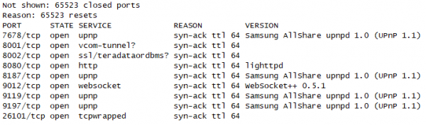
With a list of opened ports, we can now examine some of the most interesting.
UPnP
Interestingly, there are multiple UPnP services that appear to be running on the TV on a variety of different ports. Since the UPnP protocol supports discovery, we can use off-the-shelf tooling to enumerate the exposed functionality. We used the “UPnP BHunter” extension for Burp suite to do this, which is capable of performing endpoint discovery and can generate template SOAP requests that are often helpful to quickly start fuzzing.
The extension quickly discovers three services, running on the three ports that nmap identified as “upnp”:
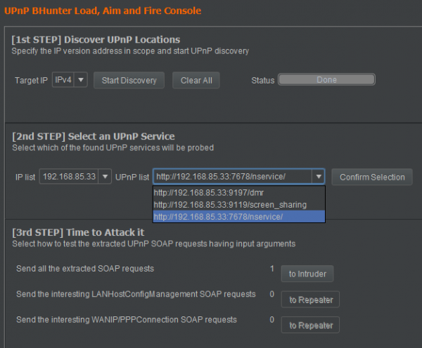
We have the following UPnP services identified:
- Port 7678 – nservice
- Port 9119 – screen_sharing
- Port 9197 – dmr
Let’s take a look at each.
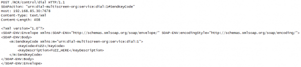
Port 7678: “nservice”
We can see from the parameter names which Burp has extracted from the UPnP metadata that some kind of “key code” is expected:
Port 9119: “screen_sharing”
In the “screen_sharing” service, on port 9119, UPnP metadata reveals that the TV receives details of an endpoint for the TV to communicate with further:
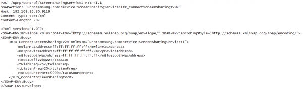
Samsung mobile devices are also known to support a screen sharing function which can work with their smart TVs.
Port 9197: “dmr”
Finally, if we observe metadata returned from the “dmr” service, we can see references to “DLNA”:
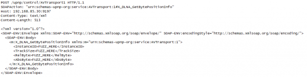
DLNA, or “Digital Living Network Alliance”, is a set of standards for sharing media between devices (for example, a mobile phone may use DLNA to mirror its screen to a TV). It defines the acronym DMR to mean “Digital Media Renderer”, which is typically a media server. It seems likely that the TV uses this service to discover and play media from sources on the network.
Checking version strings
Since UPnP exposes such rich information, including version strings, we wrote a Python script that scans for UPnP services on the network and fetches all related CVEs from https://cve.mitre.org. In its current iteration, the script simply checks version strings and does not attempt exploitation to confirm that the potential CVE is applicable to the target, and so manual verification is still required. It is available here.
The script sets up a UDP socket and creates a HTTP message using the “M-Search” HTTP method. The HTTP message is then sent to the multicast IP address 239.255.255.250 on port 1900, allowing for the discovery of all UPnP devices.
We ran this against the Samsung Q60R, and were initially excited by the large amount of matches. However, it seems that Samsung backported fixes for these bugs without updating version strings, as we were unable to exploit any of them.
Port 8080
Returning to our initial nmap scan, we can see that a HTTP server is present on port 8080. Scanning it with dirbuster did not reveal much useful information, and so we turned to the TV emulator image to see if we could find anything about it.
As mentioned above, Samsung make a qemu-based emulator available for download to support software development. This emulator comes with an x86 build of the Tizen OS, and although we suspect this image to be different in places to that on the “production” TV, it is still very useful. After installing the emulator, we can find the disk image on disk as 'C:\tizen-studio-data\emulator\vms\T-samsung-5.0-x86\emulimg-T-samsung-5.0-x86.x86', which we can convert to a raw disk via qemu-convert and then mount as a regular Linux ext filesystem.
We can soon find a lighttpd configuration file at /usr/apps/org.tizen.webserver/conf/ATSC_DVB/pluginentries.xml , which shows us some exposed URLs. Although we can’t confirm this is the configuration file used by the TV at this point, we can verify the endpoints contained in it.
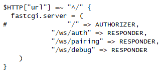
These endpoints seem interesting (with the exception of “/ws/debug”, which just shows a static debug page). They seem to deal with pairing devices with the television to allow remote control. We can further examine the TV emulator image to determine the binary that is responsible:
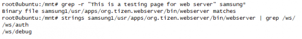
This binary is a good candidate for fuzzing and further investigation, since it handles authorization of paired devices and is accessible via the network.
Ports 8001 and 8002
Port 8002 is simply a HTTPS version of the HTTP endpoint served on port 8001.
Port 8001 is documented by Samsung as providing debug facilities for app developers. Placing the TV into “debug mode”, as documented in the preceding Samsung page, is required to make use of most of these facilities.
Samsung tell us that can access the endpoint “/api/v2/” via a web browser, and indeed we can:
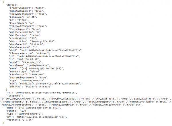
This is interesting functionality which may be of use to us during our other research.
Port 26101
This port is used by the “Samsung debug bridge” to facilitate debugging and deployment to the TV. We will look at this in detail later on.
Network surface summary
So far, we have observed open ports on the TV, located some interesting attack surface, and identified the binaries responsible. These binaries can be analysed at a later date, either by extracting them from the emulator image, or by extracting them from the TV itself. Our next work will deal with the latter task – extracting binaries from the TV.
Board-level analysis
The next aspect of the TV which we were interested in was the availability of debug facilities, intended for Samsung engineers, which we could abuse to get more information about the running environment. We had initially hoped that it would be easy to get a shell by connecting to debug traces on the board, but this proved unexpectedly difficult. However, our analysis revealed many other interesting details about the system.
Looking for debug ports
Some research into previous Samsung TVs shows the presence of a “service port”, a 3.5mm jack which carries an RS232 signal. This service port, once enabled in the TV’s service menu, allows the user to tweak a variety of settings not normally available, and view a plethora of debug information – see the samygo wiki for information about it.
However, a quick look at the physical connectors on the Q60R series shows that no such port is physically present. We thought it seemed likely that the port was still available, just without a physical jack connected to the board – and so our analysis of the board began.
Once we remove the back cover from the TV, the innards are clean and simple. There’s a power supply board, located on the right-hand side of the TV. This is responsible for generating both the clean DC that the main board operates at, and the high voltage used for the backlight of the display panel – for this reason, care should be taken to avoid a nasty electrical shock when it is disconnected. Much more interesting to us is the board on the left, which houses almost all the “smarts” of the TV. Once we remove it from the TV, and remove the aluminium heatsink, we can get a good look at it:
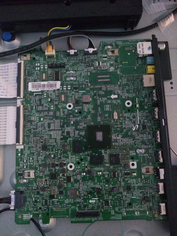
There are a lot of interesting things on this board - from clues in the silkscreen to unpopulated connectors with interesting captions! Let’s start by identifying some of the main ICs and looking for interesting connectors.

| A | SoC debug connector |
| B | Main SoC |
| C | K4F8E30, 1GByte DRAM |
| D | 25Q40CLSIP, SPI flash |
| E | 25Q80DVSIG, SPI flash |
| F | SDINBDG4-8G, eMMC flash (8GByte) |
| G | “cn1502_serif” |
| H | “cn701_db” (underside) |
| I | “cn2300_cx_db” |
| A | “CN701_DB” |
| B | “UART_RX_SW” and “UART_TX_SW” |
The large chip near the centre of the board, designated “B” here, is likely the main SoC (“System-on-chip”) that powers the board. We can see two DRAM chips near it (“C”), sized at 1GByte each, which are almost certainly main system RAM. Next to those, there is an eMMC flash chip (“F”). This is likely where the root filesystem is stored. There are some other flash chips on the board – such as D and F – but they are quite small, at 512KByte and 1Mbyte, so they are probably used to store settings internal to the TV’s non-smart functionality, such as calibration and settings for the QLED panel, or DDC information, which is used to identify the TV when connected via HDMI.
While the enormous SoC debug connector (“A”) looks very tempting, it requires some expensive proprietary tooling to connect to, and so we didn’t investigate it further. It likely carries high-speed signals straight from the SoC’s system bus and so would require high-speed electronics to operate.
Finally, near the bottom of the board, I’ve highlighted three unpopulated connectors. The leftmost is marked as “cn1502_serif” in the board silkscreen, which may indicate it is used for a serial interface of some kind. On the right-hand side, there is cn2300_CX_DB.
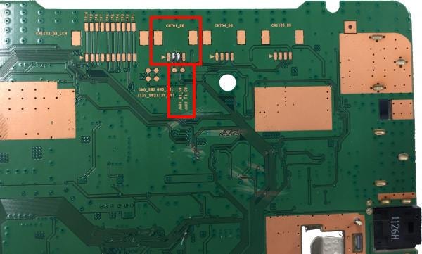
Finally, if you look at the underside of the board, you will see an unpopulated connector footprint, labelled CON701_DB. Immediately below it (and connected to it) are to two test points, marked “uart_tx_sw” and “uart_rx_sw”, suggesting they connect to a software UART (ie, a serial port). If you trace where these test points connect, you will discover they each connect to a resistor (r1512ex and r1513ex) and then to an unpopulated IC footprint (designated IC702_RS). Usually, when a device requires an RS232 port, a level shifter will be used to convert the TTL logic signals into the higher voltages that RS232 requires. It seems likely that is what is happening here – the unpopulated IC is likely a level shifter. Observing the IC footprint further, we can see that two of the pins connect to main SoC. These are likely to be the TTL-level logic signals which would normally be turned into RS232, if the level-shifting IC were present. We can simply connect to those signals and process them ourselves.
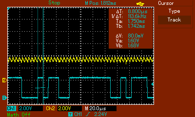
Of course, we aren’t reckless enough to connect these ports directly to a computer without doing further validation of our theory. Let’s attach an oscilloscope to observe the behaviour of these pins during a system boot. In blue, we have the signal we suspect is serial output from the TV, and in yellow, the signal we suspect is serial input to the TV.

We can see a nice binary waveform here, containing the binary 1’s and 0’s that a low-voltage serial line would contain. Note the peak-to-peak voltage of around 3.5v (top right), which corresponds to a TTL signal level. We can also measure the lengths of the pulses via the oscilloscope (see image below), which reveals a pulse width of approximately 8.8 microseconds. From this, we can work out the baud rate of the signal – simply divide 1 second by 8.6 microseconds, which results in 113636. Given the wide tolerance of most serial UARTs, this is almost certainly a 115200 baud signal.
Now that we have validated our theory, we go ahead and connect to a cheap USB-to-TTL serial adaptor, and then open a terminal in minicom. We’re greeted with the following:
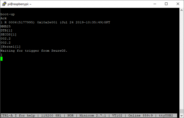
Clean ASCII! This verifies that we’re connected to the debug port properly, although the text we receive is not very interesting yet – more on this later.
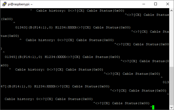
We can also connect to the second serial port – CN2300_CX_DB – in a similar manner. It is much less interesting, though, presenting only the following ASCII values repeatedly:
Enabling debug mode
Let’s turn our attention back to the first port. If you recall, the SamyGO wiki tells us that we can enable debug mode via a hidden service menu to get some information. This service menu isn’t intended to be accessed by an end-user. Samsung engineers can enter this menu using a special remote control, which has a button marked “factory”. Although we don’t possess one, we can still access the menu - there are a few different ways to transmit this code, and since we already have LIRC set up via a USB IR Toy, it’s easy for us. We can simply send the “factory” code followed by the “info” code via the web UI. Once we do this, we get a service menu displayed on the screen of the TV:
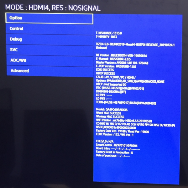
And from here we can set the “RS232 mode” (found under the ‘control’ and then ‘sub’ menus) to “debug”. Next time we reboot the television, we are rewarded with a plethora of debug information from the serial console:
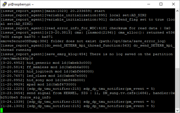
While the SamyGO wiki advises that we can enter a “TDM code” into the serial console to get to some further service menus, none of the codes they supply on their wiki had any effect on our Q60 series. It might seem that we’re out of luck, but an eagle-eyed viewer may notice that the code is already printed to the debug console – as part of the kernel command line!
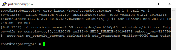
Yes, that “SELP_ENABLE” parameter contains the code we need. If we type that code, 20196873, into the serial port, and hit enter, the console will become active and what we type will be echoed back to us. If we then type the usual TDM code, as used by all other models of TV – 20089999 – we can see with the TDM debug menu:
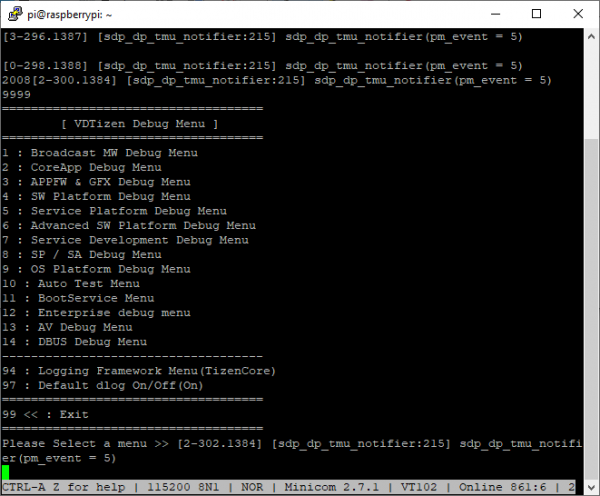
Unfortunately, however, there are no options in this menu that are of any use on our quest to get a shell. The emulator contains a different build of the debug menu, which contains an option to simply spawn bash – but that option is not built into the binary on the TV. We can, however, enable a large amount of debugging information which might be useful later on – and we are hopeful that details of the TDM console are useful to the community at large, even if they don’t yield our desired shell.
Dumping flash memory
Since our attempts to get shell access have so far proved unsuccessful, we explored the possibility of obtaining an image of the root filesystem which we could analyse. Of course, firmware upgrades are available for download from Samsung’s website, but unfortunately, they appear to be encrypted – and so we returned our attention to the board itself.
We previously observed a large 8GByte flash chip on the board, speculating that it is likely to contain firmware of some kind. Its large size suggests it holds the root filesystem and possibly the kernel for the operating system, and so we set out to dump its contents.
One thing I would like to point out here is that we didn’t know, at this stage, if the flash chip contained encrypted data or not. Since the downloads provided by Samsung were encrypted, there was a chance that the flash chip simply stores encrypted data which is transparently decrypted on-the-fly by the SoC prior to any access. This behaviour is quite common in complex devices such as games consoles.
Nevertheless, we set about researching this flash chip. We can only find very brief information about it from the IC vendor, Sandisk. A single-page overview is available at their site https://www.sandisk.com/content/dam/sandisk-main/en_us/assets/resources/data-sheets/iNAND-7250-Industrial-PB.pdf but no datasheet is available freely.
This overview does tell us a few things, though. Firstly, it tells us that the IC itself performs “ECC, wear levelling, and bad block management” – good news for us, as if the main SoC performs these duties, it will be much more difficult for us to implement that functionality (which is necessary to make sense of the data on the chip). Even better, though, is the news that the chip interface is “eMMC 5.1 HS400” – this is an open standard, meaning that we will not need to reverse-engineer any proprietary communication protocol.
Things get even better, though. “eMMC” is simply an embedded form factor for the MMC standard, and readers may recognize MMC as being a subset of the “SD Card” that we all know and use regularly – which means that if we can connect the chip directly to an SD card reader, we can simply read it using regular tools! What’s more, the eMMC standard includes the pinout of the IC, so we don’t even need to reverse engineer the connector.
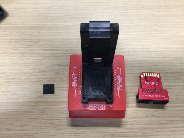
The package that the chip uses is FBGA, with 0.5mm spacing between balls. This is too fine for me to comfortably hand solder, so we simply bought a ZIF socket, which came with a handy SD card connector which we can simply plug into a card reader. From left to right, we have the eMMC chip itself, the ZIF socket, and the SD card adapter:
After we spent some time cleaning the underside of the desoldered IC enough for a reliable connection, the connected computer could read the chip with no further problems, and we could proceed to image it, leading the another piece of good news – the data on the eMMC chip is not encrypted, and we can proceed to examine it!
Looking at partitions
So, we have successfully dumped the eMMC chip on the TV to a file for processing. It seems like this means our quest to read the files on it is at an end, but unfortunately, this is not the case – still further work is necessary!
Taking a look at the filesystem (“fdisk -l img.raw”) reveals a complex structure, with 22 partitions. As we did before for the emulator image, we use kpartx to make each accessible from the disk image, and then we can proceed to use the Linux ‘hexdump’ tool to examine them. We quickly find that around half of the partitions contain only zeros - likely an indication that these partitions are used only for backup space during a firmware upgrade (or perhaps for alignment between partitions). Either way, we can ignore these partitions for our analysis.
Next, we can use a combination of the ever-useful binwalk tool and a brief hexdump to identify some of the other partitions:
| Partition | Size | Contents | Notes |
| 1 | 512 KB | ||
| 3 | 2 MB | ||
| 5 | 15 MB | uBoot kernel | See binwalk output |
| 7 | 1 MB | ||
| 9 | 64 KB | Contains string “__salted”, indicating OpenSSL data | |
| 11 | 64 KB | Contains TV model number and string “$MMC_OTP” | |
| 12 | 2 MB | Little endian ARM code, 16-bit Thumb | See “binwalk -Y” |
| 14 | 1 MB | ||
| 17 | 12 MB | VDFS | Partitions start with bytes “VDFS2007” |
| 18 | 1.6 GB | ||
| 20 | 20 MB | ||
| 21 | 4.1 GB |
We can see that partition 5 contains a Linux kernel image, wrapped in a “uBoot header”. uBoot, or “Das U-Boot”, is a bootloader commonly used in embedded devices, such as mobile phones or games consoles, so it makes sense that Samsung would use it. uBoot is open source, and so if you’re interested you can find out more at their GitHub.
Partition 9 is interesting because it seems to contain encrypted data, but beyond that, we don’t have much information about it.
Partition 12 looks to contain code of some form, and if we use Binwalk’s “-Y” option - which uses a disassembler to identify the CPU architecture – we find that it contains a large chunk of ARM code. This makes sense, since the TV mostly uses the ARM architecture, although its purpose remains a mystery for now.
Finally, there are four partitions which bear the magic string “VDFS2007”. One of them is a whopping 4.1GB, and another 1.6GB, so it is likely that these contain the root filesystem. Unfortunately, though, we can’t mount them using any of the common filesystem mounting tools. What now?! We have the data, but we can’t read it!
VDFS
A little research reveals that “VDFS” is the name of Samsung’s proprietary filesystem, an abbreviation of “Vertically Deliberate File System” (not to be confused with VMWare’s similarly-named “vDFS” filesystem). It is undocumented and information is scarce, but fortunately a very old version of a filesystem driver can be found for download at Sourceforge. Building this driver is simple, but due to its age, requires a relatively old kernel – we used an Ubuntu Saucy distribution, with a 3.9.9 kernel for this.
Once this driver is compiled and installed, we can mount the VDFS filesystem without problems. While it appears once again that we have reached our objective, this is not the case! Attempting to read some files will succeed, but many other files are unreadable, as the driver will complain about a versioning error.
Checking in dmesg, we can see the VDFS driver is unhappy about the version of a structure on the filesystem. It is likely that these files can only be read by a newer version of the VDFS driver. Fortunately, we have a newer version available to us – the binary in the kernel’s uImage. Our next step is to do some analysis of this driver, and ascertain enough information about the updated structure to allow us to read the entirety of the filesystem.
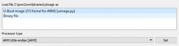
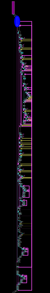
Firstly, let’s load the contents of partition 5 – the uImage – into IDA. IDA is smart enough to detect the format of the image – a U-boot image – and to extract basic information about it. Just hit OK and wait for the initial analysis to finish.
Unfortunately, once autoanalysis completes, there are still a lot of regions that IDA hasn’t identified. If you look at the IDA’s “Navigator” bar (above), you can see a lot of orange stripes – which indicate portions that IDA has identified as containing code, but is unable to attribute to a function. Our first task will be fixing up this disassembly.
If you take a quick glance over the code, you’ll see many pointers (inline with the code) which cannot be resolved. For example, here are the first few – they are at very high memory locations (over 0xC0000000) and IDA cannot follow them.
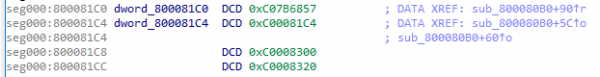
This is produced by the way that U-Boot loads. While IDA has (correctly) ascertained that the U-Boot kernel is loaded at the base address 0x80008000, the first thing that U-Boot will do is to copy itself to the 0xC0008000 range, and run from there. Thus, the pointer to 0xC0008300 we see above will point to the memory which IDA has loaded at to 0x80008300. IDA includes functionality to change the base address of the loaded data (known as “Rebasing”), so invoke that via the “Rebase Program” menu (under “Edit” and then “Segments”). Change the address form 0x80008000 to 0xC0008000, untick “Fix up the program”, and hit OK. Now, if you highlight the “0xC0008300” pointer and hit enter, IDA will display the correct data.
While this gets us part of the way, the navigator bar still reveals that we have a large amount of code which has remained unattached to a function. To investigate why, jump to a place that has a function start (such as 0xc0015fb0) and hit the ‘p’ key to create a function – you’ll notice the following in IDA’s log panel:
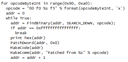
This is because IDA has failed to disassemble the opcode at the given address. The opcode in question, 0xF590F000, is seemingly not recognized by IDA’s ARM engine. While it is possible to modify the CPU library that IDA uses to add support, for our case this is not really necessary – all we’re interested in is getting a clean disassembly for us to reverse – so we can just patch out occurrences of this mystery opcode and replace them all with NOPs. If we repeat this procedure a few times, we learn that there are 16 opcodes which IDA does not disassemble, all in the F59xF000 range. Let’s write some IDAPython to patch all these instances:
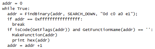
Next, we use IDAPython once again. This time, we simply look for the “MOV R12, SP” instruction, usually used to start a function, and force IDA to define a function at each location. This may result in some false positives, but is sufficient for us to reconstruct code flow. This is the code we use:
Finally, the navigation bar is a nice blue, indicating that IDA has made sense of the binary somewhat. Our analysis can continue.
Searching IDA’s “Strings” dialog for the string “VDFS4” reveals lots of debug messages. Some of them have been correctly associated with the code that uses them, such as “btree_traverse_level”, which leads us to this location in the code flow:
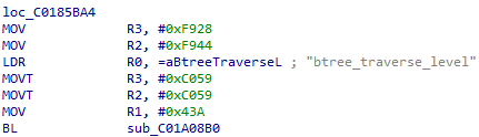
This code is setting R2 to 0xC059F928, via two 16-bit loads. One quirk of ARM is that it has no 32-bit MOV instruction, and so this pattern is very common. If we follow this pointer, we find that the code is calling the function at 0xC01A08B0 and passing the strings “btree_traverse_level”, “!record || IS_ERR(record)”, and “vdfs4-ERROR:” . If we look through the source code we obtained from Sourceforge, we can find this call as originating from the IS_ERR macro in the btree_traverse_level function (btree.c line 1026).
Since the IS_ERR macro expands to a call to VDFS4_ERR, it seems likely that the function at 0xC01A08B0 is VDFS4_ERR. Since the function is always called with the name of the caller – for example, “btree_traverse_level” above – it is a quick and easy way to identify functions. One caller passes the argument “vdfs4_init_file_decompression”, which (as we can tell from the source code) is responsible for checking the supported filesystem. If we take a look at the start of that function in IDA, we can see that support has been added for version six of the filesystem, while the code we obtained from Sourceforge supports only version 4:
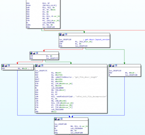
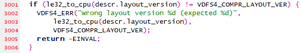
We can see a comparison with the integer value 5, and then a comparison with 6. If neither check succeeds, an error path is taken (the large block in the middle).
If we analyse this function further, however, we can determine the significance of the two other blocks, which load R6 with either 0x20 (for VDFS version 5) or 0x28 (for VDFS version 6). This is the size of a structure used to describe the inode in question. We can tweak the Sourceforge driver, adding this code:
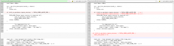
Now, when we build, we are able to access every file in the filesystem! Obviously, this quick hack to the VDFS driver is not something we could depend on in a production workload, but is fine for our purposes of analysis (especially since files are checksummed by VDFS itself after they are decompressed). Our analysis can continue!
Once we mount the four VDFS partitions, we can see that one in particular – partition 18 – appears to contain a Linux-style filesystem layout. Furthermore, there appears to be some information left over from the manufacturing process. For example, there is a file in “/etc/include” named “partition.txt” which is most enlightening:
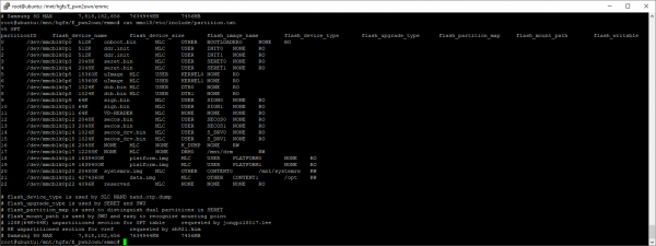
This file appears to reveal the filenames used to program the individual partitions. Here’s a reformatted version, which is slightly easier to read:
| Partition | Size | Image name | flash_ upgrade_type | flash_ partition_map | Mountpoint | Access |
| 0 | 512KB | onboot.bin | OTHER | BOOT LOADER0 | ||
| 1 | 512KB | ddr.init | USER | INIT0 | ||
| 2 | 512KB | ddr.init | USER | INIT1 | ||
| 3 | 2048KB | seret.bin | USER | SERET0 | ||
| 4 | 2048KB | seret.bin | USER | SERET1 | ||
| 5 | 15360KB | uImage | USER | KERNEL0 | ||
| 6 | 15360KB | uImage | USER | KERNEL1 | ||
| 7 | 1024KB | dtb.bin | USER | DTB0 | ||
| 8 | 1024KB | dtb.bin | USER | DTB1 | ||
| 9 | 64KB | sign.bin | USER | SIGN0 | ||
| 10 | 64KB | sign.bin | USER | SIGN1 | ||
| 11 | 64KB | VD-HEADER | ||||
| 12 | 2048KB | secos.bin | USER | SECOS0 | ||
| 13 | 2048KB | secos.bin | USER | SECOS1 | ||
| 14 | 1024KB | secos_drv.bin | USER | S_DRV0 | ||
| 15 | 1024KB | secos_drv.bin | USER | S_DRV1 | ||
| 16 | 2048KB | K_DUMP | Read-write | |||
| 17 | 12288KB | DRM0 | /mnt/drm | Read-write | ||
| 18 | 1638400KB | platform.img | USER | PLATFORM0 | ||
| 19 | 1638400KB | platform.img | USER | PLATFORM1 | ||
| 20 | 20480KB | systemrw.img | OTHER | CONTENT0 | /mnt/ systemrw | Read-write |
| 21 | 4274360KB | data.img | OTHER | CONTENT1 | /OPT | Read-write |
| 22 | 4096KB | reserved |
Note the “flash upgrade type” which seems to confirm our hypothesis that seemingly-unused partitions are used for backup images during upgrades.
Also interesting is partition 12, “secos.bin”. If you recall from earlier, we used binwalk to identify some ARM code in this partition. It seems likely that this data is transmitted to a microcontroller on the board, outside of the main SoC, to perform some security-related duty.
We also get a little bit more information about the four VDFS partitions. We can see that partition 17 is mounted at /mnt/drm, 20 is mounted in /mnt/systemrw, and 21 in /opt. With this, we can reconstruct the whole filesystem and our analysis of userland binaries can continue.
However, there is still more information we can extract from this table! We can determine a lot about the memory layout of the TV from partition 7.
Hardware layout and details
Note that partition 7 is programmed from a file named “dtb.bin”. A DTB, or “Device Tree Blob”, is a structure that is used by uBoot and the Linux kernel to describe various aspects of the target board. Typically, these are compiled using a special compiler from a domain-specific language. Tools to dump a DTB are present in most Linux distributions, so we can go ahead and dump it with "dtc -I dtb -O dts -o dumped.dts mmc7.raw".
The output of this file is most enlightening – giving us a complete memory map of the system and various hardware devices! It also reveals the SoC name in the TV’s version string – “Samsung DTV based on SDP1801(Muse-M) SoC”.
One aspect we were particularly interested in was the ability to run the binaries from the TV inside an emulated environment. While Samsung makes an x86 emulator (and associated filesystem images) available, we felt that it was likely that the binaries on the TV contain more attack surface (and potentially backdoors) than the binaries bundled with the emulator (or built from the public source available from Samsung). While some binaries from the TV can be executed on an ARM Linux system (such as a Raspberry Pi), complex systems that depend on other services are difficult to run accurately. However, now that we have this level of information about the TV, we may be able to build an emulator capable of booting the kernel we extracted from the eMMC chip – which would open up many possibilities for further research, as other researchers could easily run the production binaries without purchasing Samsung hardware, or could instantiate many instances of the emulator for high-volume fuzzing. Once we have source for the emulator, it is even possible to instrument the emulator to yield fine-grained coverage information which we can feed into our fuzzer.
Firmware upgrade process
One of the steps in analyzing devices such as TVs - the more sophisticated, "consumer-ready" systems - is diving into the update process. As new functionalities, security fixes etc. need to be deployed onto production appliances, having such a process in place is a must-have.
For Samsung TVs, two options worth mentioning are available. Firstly, the online update: packages are downloaded from servers managed by Samsung and (fortunately for customers) cannot be easily intercepted for inspection. Any attempts to do so will result in the TV rejecting the connection.
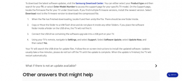
Fortunately for anyone performing the analysis, however - and customers without an Internet connection - another option is available as well. The package can be downloaded from an official Samsung website and moved onto a flash drive. This flash drive - assuming it contains a valid FAT/exFAT filesystem - can then be used to perform the update process.
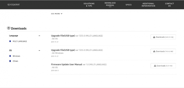
Lets download the package ourselves, and inspect its contents:
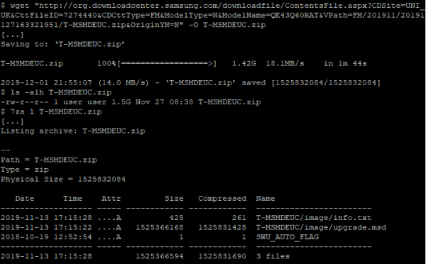
It is worth noting that the package, contrary to the online update on the TV itself, is downloaded over an insecure HTTP connection.
Also worth mentioning is the fact that files are stored in a directory called `T-MSMDEUC` - this is the device code that might aid us in the analysis. It corresponds to the model code printed on the PCB itself – “MUSE_M”.
In the “image” directory, along with the “info.txt” file, is the most interesting part. A file named “upgrade.msd” contains the actual firmware that will be deployed onto the device. Let’s check what file we are dealing with, using our old friend the “file” utility:
Huh, “file” does not seem to know. Let’s take a quick look at the file header:
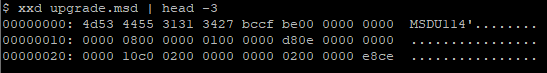
The `MSDU11` string appears to be the “magic” value of the format. MSD, then, appears to be a proprietary Samsung file format. Having extracted the firmware from the eMMC chip previously, we can check if this string, “MSDU11”, or “upgrade.msd”, are referenced anywhere within the filesystem.
It seems that “SWUCoreTV” seems to the most likely candidate for a more thorough inspection! Time to fire up our favourite disassembler (in this case, Ghidra) and go to work.
First, lets look for the former string, “MSDU11”. There is just one function referencing it (although a few times) – with the promising name of “searchForUpgrade” (SWU::Core::Strategies::CUSBSearchingStrategy::searchForUpgrade(SWU::SWUCommon::ServiceTransactionType). No calls to this exact function are made, although it is still worth inspecting, especially given how convoluted the logic there is:
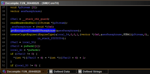
One of the first interesting functions - an unnamed one, at that - is `FUN_00401F04`. It calls a ton of functions related to parsing the file - bingo! Just what we were looking for.
The most interesting function - as we want to decrypt the firmware - would be `getEncryptedItemsAESPassphrase`. That function does not seem to contain any logic worth mentioning, though. We can, however, check the functions around the place where `getEncryptedItemsAESPassphrase` is called, as they are likely to be related. In there we can see the following:
`createCryptEngine` looks interesting! Let us dive into this function next:
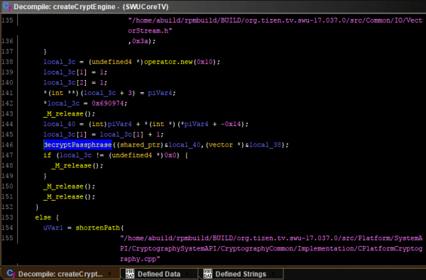
Down the rabbit hole we go! `decryptedPassphrase` does not leave us much hope anymore, though:
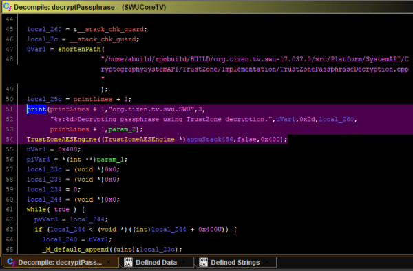
As we can see, the AES passphrase used is decrypted using a secure enclave (TrustZone). Unless device access is gained - enabling us to use the shell - the firmware passphrase (and thus the firmware itself) cannot be easily decrypted.
SDBD
As we noted earlier, the TV is listening for TCP connections on port 26101.
This port is documented by Samsung as used for the “sdb” server. If you’re familiar with Android development, this might sound a little familiar, since Android provides a similar “adb” (or Android Debug Bridge) command. We can find the client tools in the client SDK, and try to use it to connect to the TV:
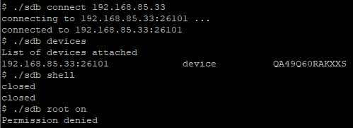
We can see that we get a connection OK, and are able to see the model number of the TV.. but our requests to open a shell or to enable root privileges were unsuccessful! Well, no cookies for us right away. We can, however, take a look at the binary (“/sbin/sdbd”) and/or analyse the source. Let us go with the latter.
Of course, the process of looking for issues in binaries/code is not as simple as picking a location (or a single function) and finding a bug there. It is meticulous work of going back and forth through function calls, analyzing parameters, the context, going up and down call trees... it is a lot of reading, basically. We can, however, do a fast-forward - as we are armed in experience and the power of post writers - and jump right to the most interesting part.
Thus, let us jump straight to “execve” references. Why? Well, if improperly used, `execve` can be equivalent to “system” - and result in command injection. Let us take a look at this particular function calling `execve`:
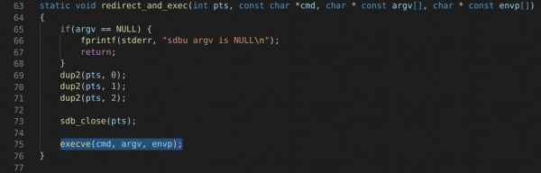
Clean and simple - and yet still prone to errors. The next step is to go up the call tree, observing calls to this function.
In `services.c` we can find such a call to `redirect_and_exec`:
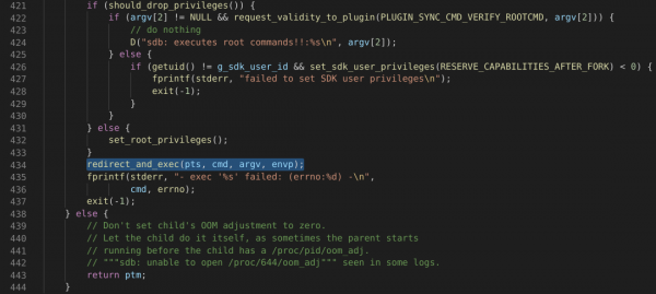
Yet again - no luck figuring out the arguments. Up the tree we go! This time to “default_plugin_appcmd.c”, within “exec_appcmd_shell_process(appcmd_info* p_info)”:
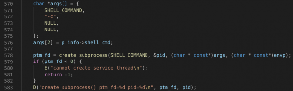
Hold on a second! This code essentially calls “/bin/sh -c “ and provides it a user argument – appearing ripe for command injection vulnerabilities! Now we just need to know whether arguments are pre-processed somehow to prevent such attacks:
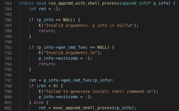
Unfortunately, it seems it is – “gen_cmd_func” from “p_info” is called, which performs escaping of shell characters. All other callers follow the same pattern.
If we take a closer look at “gen_cmd_func”, we can see that all our arguments are processed with `parse_arg` first. This function is defined as follows:
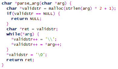
Each character is prepended with a backslash (`\`) effectively rendering any special characters ineffective (oh, the irony!). Thus, unfortunately, our journey ends here. Despite the (un)safe “system”-like “execve” usage, we cannot inject any commands here. We could use some function parameters against it (for running additional commands spawned from the binary run, for example), but this proved fruitless as well.
Summary
We sincerely hope that it inspires the community to continue our work – while nothing that our team did yielded any real vulnerabilities (in contrast to another F-Secure team), it is hoped that the groundwork that we’ve done is enough to accelerate any independent analysis.
Anyone inspired by the research is encouraged to analyse any area they see fit – from the remote control, through to the websocket API and SDB, there is a huge amount of still unexamined attack surface. Happy hunting!
Credits
This was, of course, a team effort, intended mostly to facilitate knowledge transfer and have a bit of fun with the "research time" that F-Secure employees have allocated. The team comprised of the following people, who all contributed in one way or another:
- Aliz Hammond
- Barnabas Tan
- Chunqi Zhu
- Darren Pang
- Krzysztof Marciniak
- Lacie Fan
- Lucas Tay
- Ming Xuan Chai
- Samuel Pua
- Wee-Jing Chung
- Wei Jie Ong
And finally, it would be remiss not to mention the "usual" pwn2own team, and particularly Mark Barnes for his assistance!